NOTE: I am not at liberty to redistribute the documentation used to build this model.
Making Clean Cuts in Catmull-Clark Surfaces:
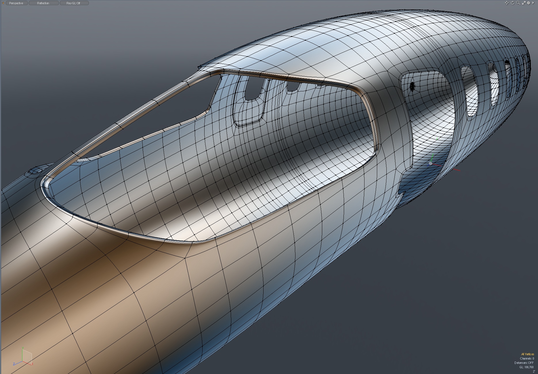
When you look at an image such as the first one below, it looks deceptively simple. Arriving at that point isn't so simple though, and is something we often struggle with in sub-d. Even if we successfully connect the various shapes, smoothing errors can creep into our renders, so maintaining our polygon flow is a key part of the process. This is a case where you can't just think "locally". Consider the standard example of taking a simple cylinder and cutting a hole in it for a tutorial. That's easy.
Consider this avalanche of possibilities. What if the opening we want to make happens to be in a piece of more complex geometry, surrounding by other cuts? What if we need to preserve parts that we're cutting out? (i.e the windscreen , doors, and windows, in the fuselage below) What if the polygon flow we created when we cut away a window in the fuselage is fine, but then needs to be adjusted when we later cut out the cabin door next to it? And, when we've cut out that cabin door, (and the emergency exit on the opposite side) our fuselage is no longer bilaterally symmetrical, so we have to adjust separate edge loops on each side, and make them all work smoothly. If your goal is to end up with meshes that are all quad polygons, that's yet another element to resolve.
In sub-d "one thing leads to another", and we have to learn to see the bigger picture, and remain adaptable as the project evolves.
I used several different methods to create all the windows, doors, hatches, and vents around the aircraft. These problem-solving methods are covered in more detail in my tutorial, "Modeling with MODO, Volume Six", but I'll show some examples here, including some that didn't work well.
Below - This image is higher resolution than what's displayed in your browser. Drag it to your desktop to view it more detail.
More prerequisites:
Before making any cuts in something like this fuselage, it pays to think about the future additions to this project. For example, we can use background constraint to add formers to the interior of the fuselage. But once we've made these cuts, that obviously becomes trickier. Now you see the reason for saving our initial, uncut fuselage. We can reuse that often in the process, and then simply remove the parts that appear in the cutouts.
"Cutters", in general:
I still find myself using the expression "cuts", when referring to operations like the one below, simply because that's what the visual effect is. But with this model, I've entirely abandoned the idea of using "cutters", in the usual sense. We create polygonal patterns, and use a background constraint to stick them to other parts, but they are never used as boolean-type cutters. Instead, they're joined to the underlying geometry. This is a typical approach that experienced sub-d modelers will be familiar with, and it works well. (I'll include several video examples of this in "Modeling with MODO, Volume Six".) One of the biggest advantages of this approach is that we retain our Catmull-Clark structure, and only create geometry where it's required, rather than making the surrounding mesh more dense than it needs to be.
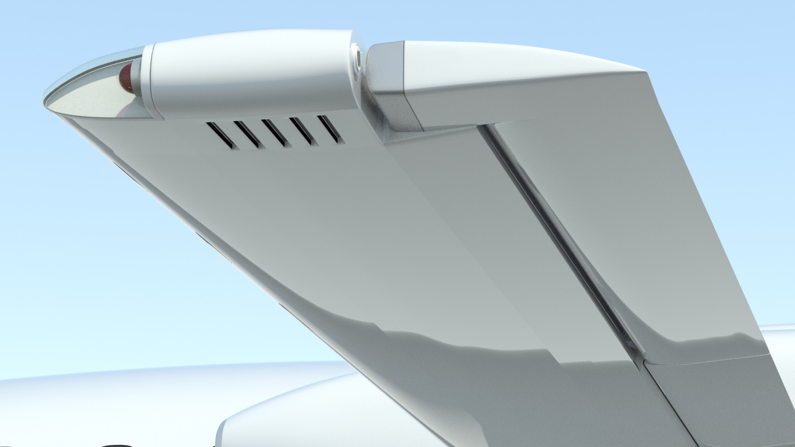
On the bottom of the P180's wing tips, there are some vents. The wing's original geometry is what I would call "medium density", and was intentionally created to include evenly-spaced polygons of roughly the same size. So, to add these vents, I used the technique mentioned above, where a "pattern" was overlaid onto the bottom of the wing, to help me figure out where polygons needed to be added, and how they could be isolated, so they didn't distort the surrounding geometry. (Remember, the images shown here are actually larger than what's displayed in your browser, so you can drag them to your dekstop for a closer look, if you like.)
Here are the finished vents in the bottom of the wing.
Below, you can see how the geometry was added, keeping the wing's surrounding polygons untouched.
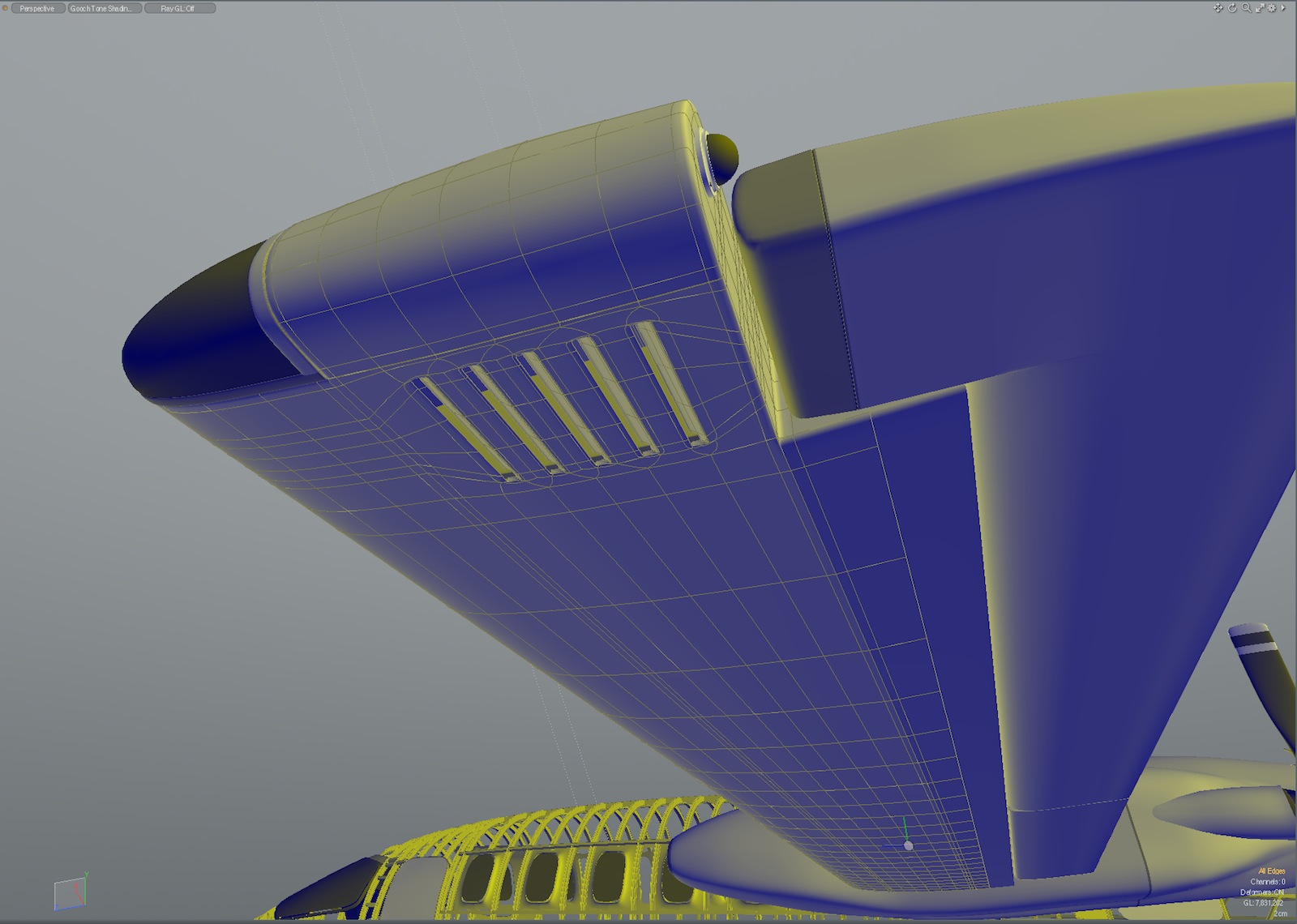
I can't emphasize enough how helpful it is to keep copies of your previous, uncut parts during this process. In the process above, we lay down our new geometry pattern with a background constraint, then delete the underlying polygons, in order to substitute our new polygons in their place. Suppose that during this process, you move some edges, or create some triangles, which adversely affects the shape you want. If you've kept a copy of the previous geometry, then you can use background constraint again, at the end of the process, to ensure that everything is the right shape. VERY handy, and practical.
Major rigging update:
All the major rigging on this model is now complete, with only some of the small control linkage parts to finish. Once those are in place, I'll be adding the "luxury" parts of the interior, including the liner, carpet, and other amenities, which will be the final steps. Click here for a video showing what's already working.
Click the "Page 04" link below, to continue.