 Sheila Wyne's "Eclipse" - Organic Modeling
There are times that I do 3D visualization work for other artists. In this case, my job (and my pleasure) was to create a scale model of my amazingly-talented artist friend Sheila Wyne's piece, called "Eclipse". It's a large organic piece, approximately 20 feet wide, 10 feet tall, and ten feet deep, installed in the lobby of the new Northrim Bank, here in Anchorage. It's composed of a variety of actual tree branches, sanded, dried, and stained, along with a 24-inch diameter, multi-layer glass disk. (Details later) This page is as much about remaining flexible for the client, as it is about modeling. It all came together in the end, and I'm pleased to have been part of it.. Thank you, Sheila!
My 3D model will never be seen by the general public. Instead, it was built to help both the artist and the engineers figure out how to safely and securely mount it in a bank where it would installed hanging from the ceiling. Here in Alaska, we have occasional earthquakes, and these things cannot be allowed to sway freely, for safety reasons. This piece occupies 200 square feet of the ceiling, and 2000 cubic feet of total area.
This was a quite a unique "scale" project, for a variety of reasons...
Why was this "tricky"?
This project outline was, "Build a scale model of this piece, based on a huge pile of photos, drawings, and measurements, to represent the actual piece, accurately enough for engineers to use as a guide to the physical installation." And, "What's required is a general scale representation of the branch's size and shape, but not to the level of individual little bumps, etc., because they'll be sanded and stained later." The image on the glass disk is an infrared image of the moon, from NASA, which was separated into 5 different colors in PhotoShop. The glass disk is composed of 5 layers of 1/4" glass, each one painted with the respective color mentioned above, then laminated into a metal band, with rubber mounting rings. The 3D model had to incorporate all that, so Sheila could show some advance images to the client. That simple fact proved to be important at times, because while MODO's "refraction depth" setting gave it a realistic look, the rendering times went way up, depicting all that transparency, reflection and (mainly) refraction.
The other caveat was that this piece was going to change somewhat, over time. For the people doing the fabrication, the same was true, because in the initial stages, before alignment holes had been drilled, it was impossible to get the piece hung exactly the same way twice. And, seeing the piece assembled, Sheila Wyne, the artist, chose to make some minor changes too. Finally, variations on the weight of the wood as it dried would affect the center of gravity. That was a bigger item than you might expect. The wood went from 250 pounds when first hung, to only about 100 pounds, after drying and staining.
The need for precision increased as time went on. What began as a semi-precise "gesture" project in 3D became an engineering tool at the end.
The Measurements:
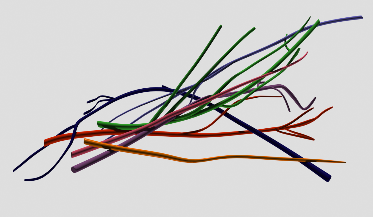
This piece consists of seven large branches, with all but two also containing several of their own smaller branches. At the time I started working on the 3D model, it had been assembled loosely, but not finalized. As you'd expect, there was no orthographic 3-view of this piece or it's components. Each branch and sub-branch had to be measured individually, then assembled in 3D. There was no "easy" way to accomplish that. Sheila and her rigger made great efforts to measure not only the lengths and diameters of the individual parts, but also various descriptions of curves and angles.
One rather obvious method of measuring the branches was to simply place them on the floor, and write notes by hand. The problem with this is that the orientation of the pieces when being measured this way is not the same as their orientation as the final art work… a true 3-dimensional puzzle. In some cases, Sheila and I resorted to all kinds of tests, to see if the pieces could be measured from the same points of view, while looking at the assembled 3D model. This is where I movable plane, along with MODO's "align workplace" feature helped. Obviously "interference issues" were a huge problem on this project, since many of the pieces had to touch, in particular ways, and yet they couldn't actually pass through each other.
Each session that Sheila and I had involved sifting through a stack of photos of the individual pieces, their measurements and notes, and tweaking the 3D model. This is a nightmare case of "One thing leads to another." Anytime we changed the orientation of one piece, everything else had to be adjusted too. That would usually lead to a third problem, and so on. During this phase, I routinely had a 4-hour session with her, followed by another 1 to 4 hours tweaking the model, and then producing both orthographic stills, and a "turntable" animation, for her to review the work. All during this phase, Sheila was back and forth with her rigger, the architects, the engineers, and the bank people too, working on the actual piece. (Busy!)
Visual Editing:
The worst mistake we made was one night when we decided to edit the file visually. Sheila felt that she knew the piece well enough, so we gave it a try. At the end of the night, She was satisfied, and I was relieved. The bad news came the next day, when I compared what we had done to known measurements, and found that we had completely screwed it up. (Aghh!) This is the classic 3D problem... As an example, if you get something looking right in the front view, you'll often find that it's wrong, in the top view. Of course, I was happy to work with Sheila, but this was becoming very difficult to edit. Patience paid off…
The Cure:
Finally, I had a chance to go out and spend all day with the piece, while it was being assembled. That particular day is the one that solved most of the problems. I took my laptop, with MODO 302, a tape measure, and a notepad, and simply spent all day measuring, taking photos, and adjusting the 3D model. What finally worked best was to create a grid with string on the ground, under the assembled piece. I then measured from the ground upward to a variety of reference points on each branch. After another couple of (shorter) sessions with Sheila, we were finished with the "branches" part of the problem.
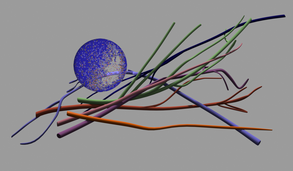
The Glass Disk:
The image on the glass disk is derived from an infrared image of the Moon, from NASA. So that it could be layered for Sheila's piece, I first separated the original images into 5 layers in PhotoShop, with each one having just a single NASA color image. Each of those plates was turned into a PNG image with an Alpha channel. In MODO, the disk was built the same way, with a "glass" texture applied to each disk piece, as well as the appropriate image map. (We tried one composite image on a single piece of glass, but didn't like the effect.) Finally, as in the real piece, a metal band was wrapped around the edges of the pieces to hold them together, and provide a means of hanging it.
Why all the bother? In real life, this layered arrangement benefits from the dimensionality, by slightly changing, based on the viewpoint, and also on the changing natural light during the day. Although the 3D model didn't have to recreate that exactly, it served as a preview for those involved.
The MODO parameters we're used to adjusting for a single piece of glass have to be changed, for something like this. We had to increase the refraction depth, for example, and control the amount and type of reflection, so that you can indeed see through the disk. When Sheila needed a sample of the disk in a hurry, I went running to the Luxology forum, and got help on the problem. (The disk had been appearing pure black, due to a too-low refraction depth.)
Not so simple…
Have a look at this screenshot of the project hierarchy. It's a lot deeper than you might expect, with several hanging methods tested. At the end, we sent several orthographic images to the engineers, so that they could decide with Sheila, which method worked best.
The Installation:
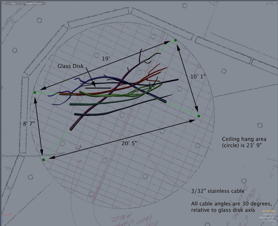
With the 3D model finished, the last step was to use a floor plan of the display area (a bank lobby) and figure out where the hanging cables needed to go. (and to be sure they could go there) Since the model was built to actual scale, we could use scanned architectural drawings as "backdrop" images in MODO. We made several versions, showing where the cables could attach, and finally selected one as the best, which was used as the installation guide.
The movie below is one of many such samples produced during the process, using color-coded hanging points to see the differences. I typically left the glass out of the "lunar disk" for these renders, to keep render times reasonable.
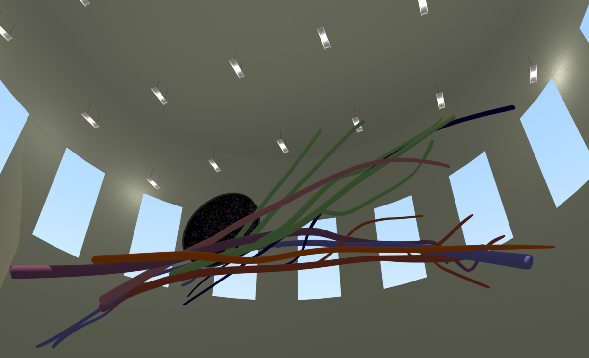
When it looked like we were finished, I did a simple render of the installation, based on the floor plan. This isn't a precision-scale model of the bank, but gives a general idea of how the piece would look from the viewer's perspective.
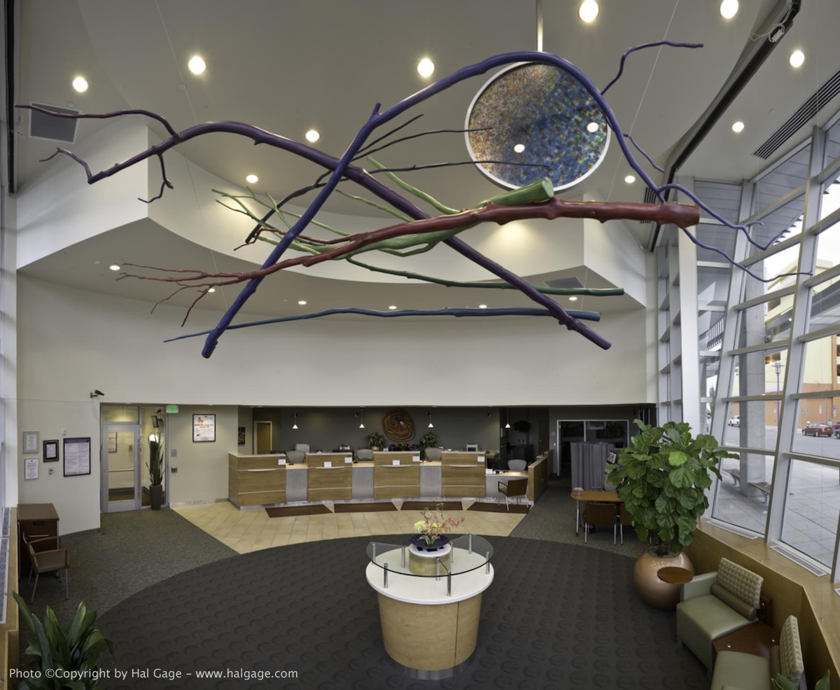
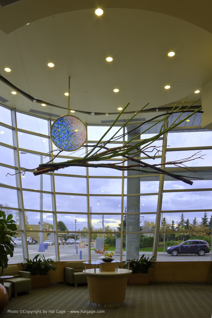
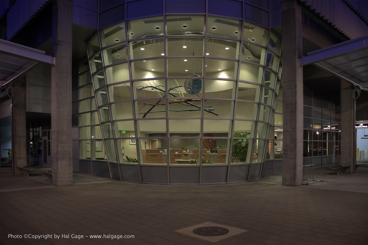
The Results!
The completed piece and it's installation are gorgeous. It benefits from quite a few natural light sources, as well as ceiling and reflected light, and as predicted, changes form, color, and apparent dimension, as you move around it. All the installation photos below were shot by photographer Hal Gage. If you copy these to your hard drive, you'll find that they're higher resolution than what's shown on this page. (typically, 1600 pixels wide)
Visit Hal's site at http://www.halgage.com