NOTE: I am not at liberty to redistribute the documentation used to build this model.
The overall "outside-in" approach:
Aircraft like this one are very smooth overall, even though they're composed of many separate parts. Since we don't have precision measurements for each of those separate parts, it makes sense to model large objects in one smooth piece, like the fuselage, and slice it up into the detailed parts as we go. I use this method on every piece of the model. The reason we do this is that in general, the exterior dimensions of the aircraft are the ones we know most precisely. So, if we model the exterior first, then we know that everything else must fit within those confines. I always model every part that has known dimensions first. That way, when we begin to guess about other parts, we already have some limits in place, and we'll know that certain things simply "must" fit within a certain area. It's a sensible approach to discovering the dimensions of unknown parts.
With that idea in mind, the first step is to create the entire exterior airframe, using the simplest geometry possible, and paying attention to the placement of the station lines on the drawings. I'll create simple, but accurate versions of the fuselage, wings, foreplane, (small wing at the front of this aircraft) vertical and horizontal stabilizers, etc., before getting into any other details, and I move very slowly at this stage. Here's why...
Suppose that you model the horizontal stabilizer before you model the vertical fin, and in your entusiasm, you go ahead and start modeling the internal ribs and spars. Then, when you do get to the vertical fin, you find that you've placed a spar right where the rudder has to go, and you're left with a lot of hard work that is now useless. So, sometimes it's best to just sit back and think about how things will be connected later, rather than diving in head first. That's why we do the complete external airframe first. Move slowly at this stage, and you can move fast later because you know your base model is right.
With the exterior airframe in place, we then build every part that has known or discoverable dimensions, and gradually build up the detail we have to guess at, around those known items. Even so, it's important to try and remain flexible, in case we discover errors along the way. (and we will, for sure!) With this in mind, try to build easily-editable parts whenever you can.
Fuselage first
I always model the fuselage of an aircraft first. It's what all the other parts attach to, so it makes sense to have this essential piece of geometry available, before moving on. It's also gratifying, because most aircraft's "personality" seems to be identified by the fuselage and windscreen shape.
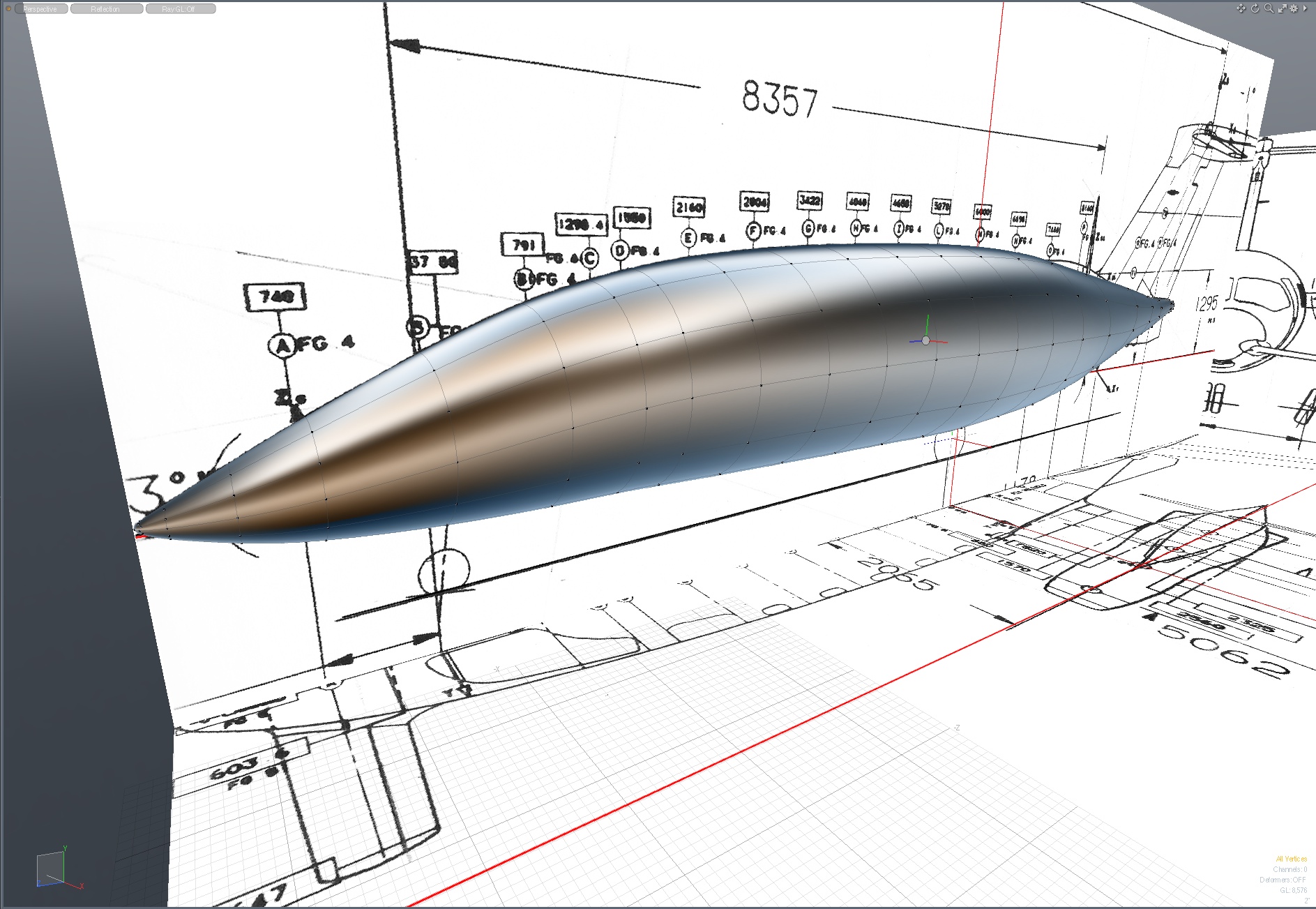
The fuselage could be created by starting with a sub-d cube or cylinder, but since I had cross section drawings, I chose to use a different method. Using the cross section drawings, I first created a single polygon for each section. These will be bridged in the next step, so it's important that they all have the same number of edges. I moved the vertices around, trying to match them as closely as possible to the section drawing, while keeping them as evenly-spaced as possible. The overall shape will change slightly when these sections are bridged, but it pays to go slowly and thoughtfully here.
Below, here are the fuselage sections bridged together, and tweaked a bit to even out the edge spacing and shape. Check this carefully in the side and top views.You may also notice that I've used the Edge Slide" tool (with Preserve Curvature" turned on, to slightly move the loops into place so they match the major (vertical) station lines on the drawing. This is part of the planning process for creating authentic details later, based on the position of those station lines, so the reasons for doing this will become clear at that point. In general, those station lines are there for a reason, such as indicating former positions, structural joints, etc.. So, since we're building those points into our initial parts, it will be easier later to add those structures in such a way that they fit well with our pre-established polygon flow.
Once this shape was as perfect as I could make it, I duplicated it, and placed it within a "folder", ("Group Locator" in MODO) labeled "ORIGINAL FUSELAGE PARTS". Importantly, this part is never edited again, during the entire course of the model. You'll see why, as we proceed.
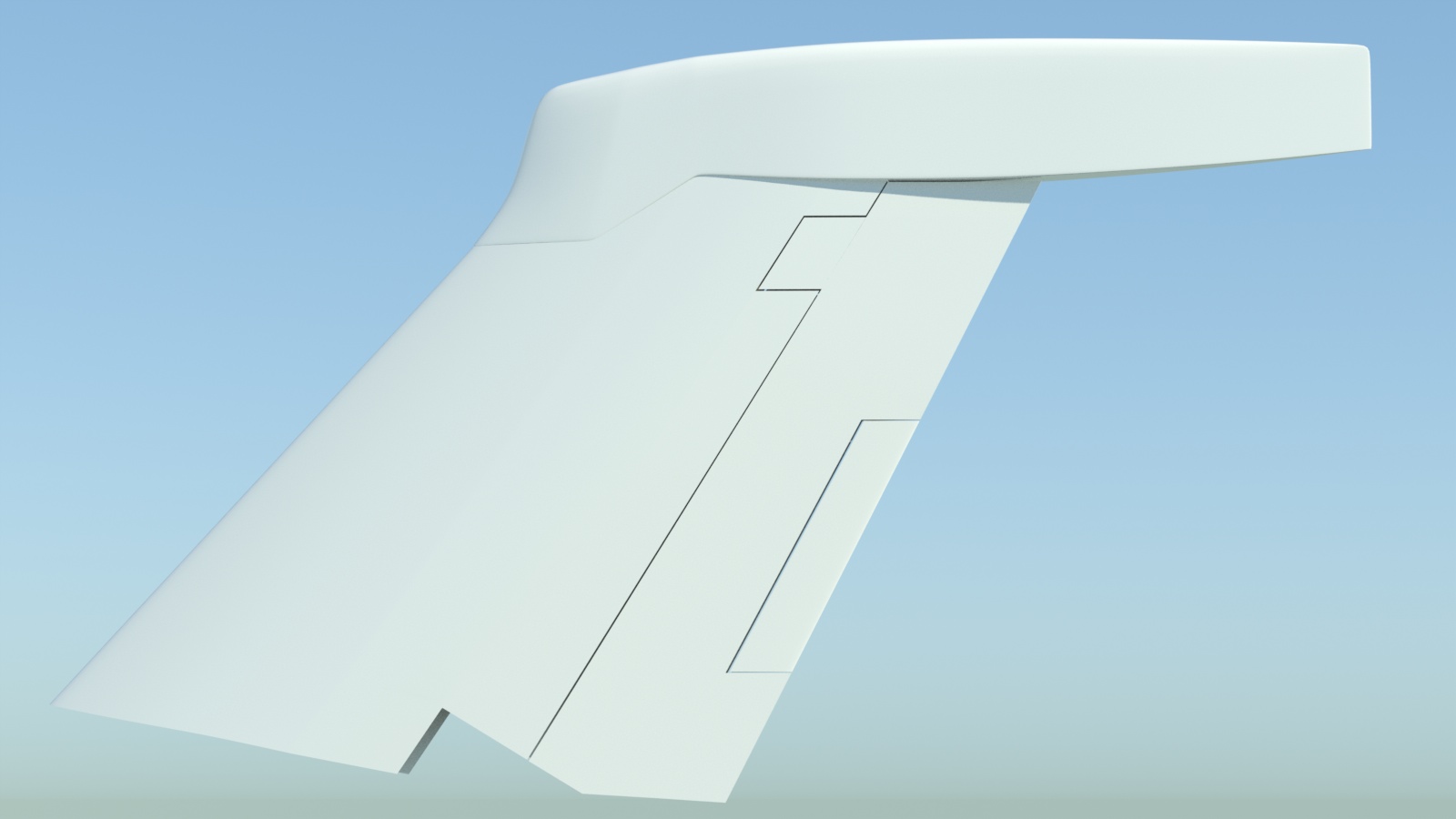
Vertical Fin/Rudder Assembly
Having already built several versions of this aircraft in the past, I'm intimately familiar with it, and know how many of the parts connect. Regardless, it's helpful to have some basic airframe parts built at this stage, to check how they relate to each other during the rest of the project. I chose to do the vertical fin and rudder parts next.
Ultimately, the vertical fin is split into three parts... the vertical fin, the rudder, and the rudder trim tab. After those are built, the fairing/cap on the top was built separately. To ensure smooth blending of those parts, I first built the vertical fin/rudder mesh in one piece, and kept this piece for future use. Often, a simple part like this comes in handy later, so save this one, create a copy, and work on that.
I then spent some time planning the location of the edge loops so that they could accommodate removing the rudder from the vertical fin, and the rudder trim tab from the rudder, with no distortion. Then I cut away the rudder and it's trim tab, and refined all three shapes. This involves placing trailing edges in the vertical fin, shaped to accept the rudder, and leading edges on the rudder, shaped to fit into the new recess in the vertical fin. When these parts are later animated, it's important that it all works as it would in real life, so those edges were shaped to fit well.
I then built the cap/fairing, which is placed at the top. Once I was happy with the shape, I cut it into three sections, as it is on the actual aircraft. Below, you can see a slightly earlier test of Psub structure, followed by a render. By working on parts this way, you ensure that the parts blend together properly, yet can be easily cut away. Later, you can remove some of the extra edge loops from the "parent" parts, and add geometry to the "sibling" parts as required.
Wings
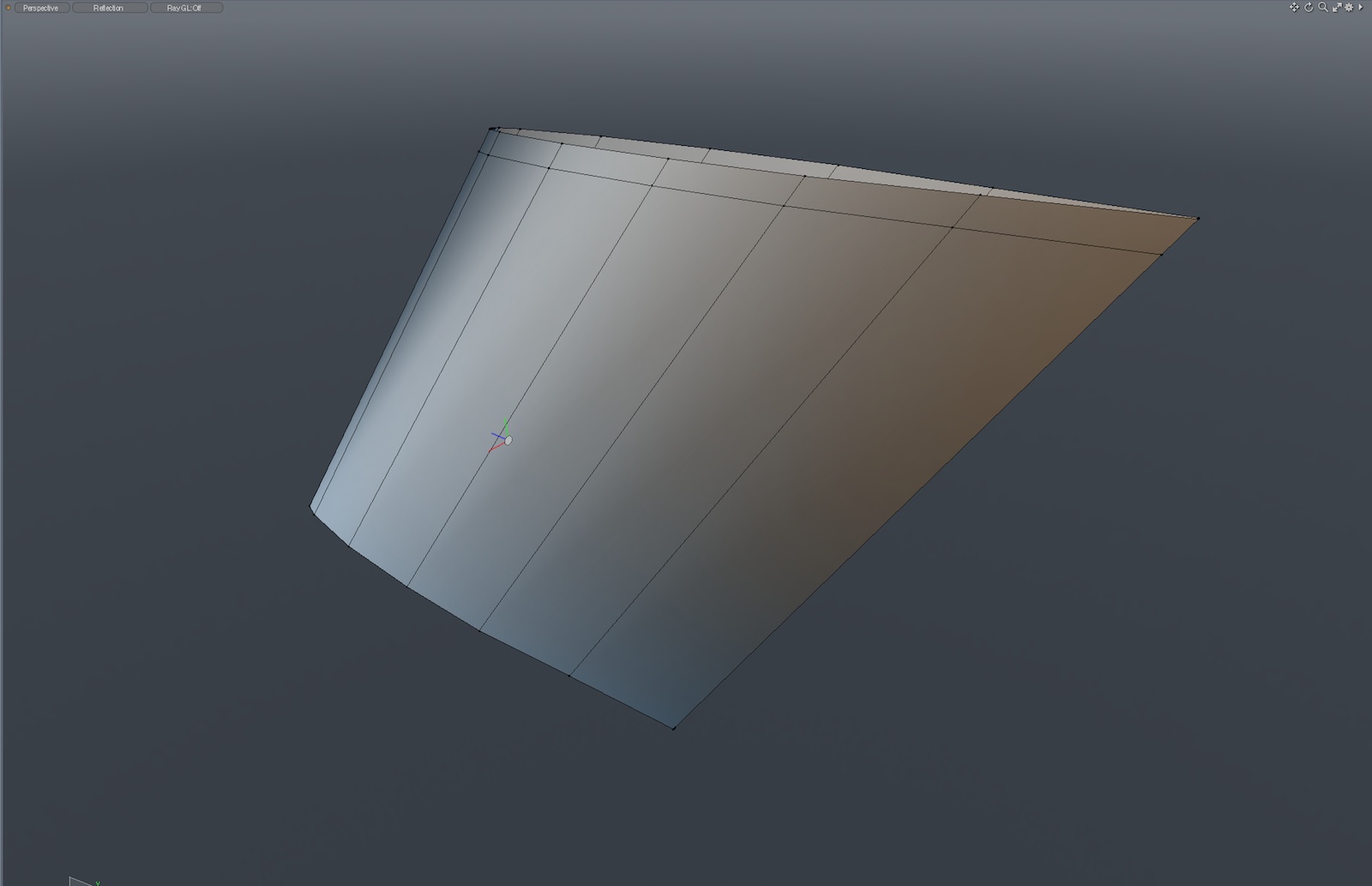
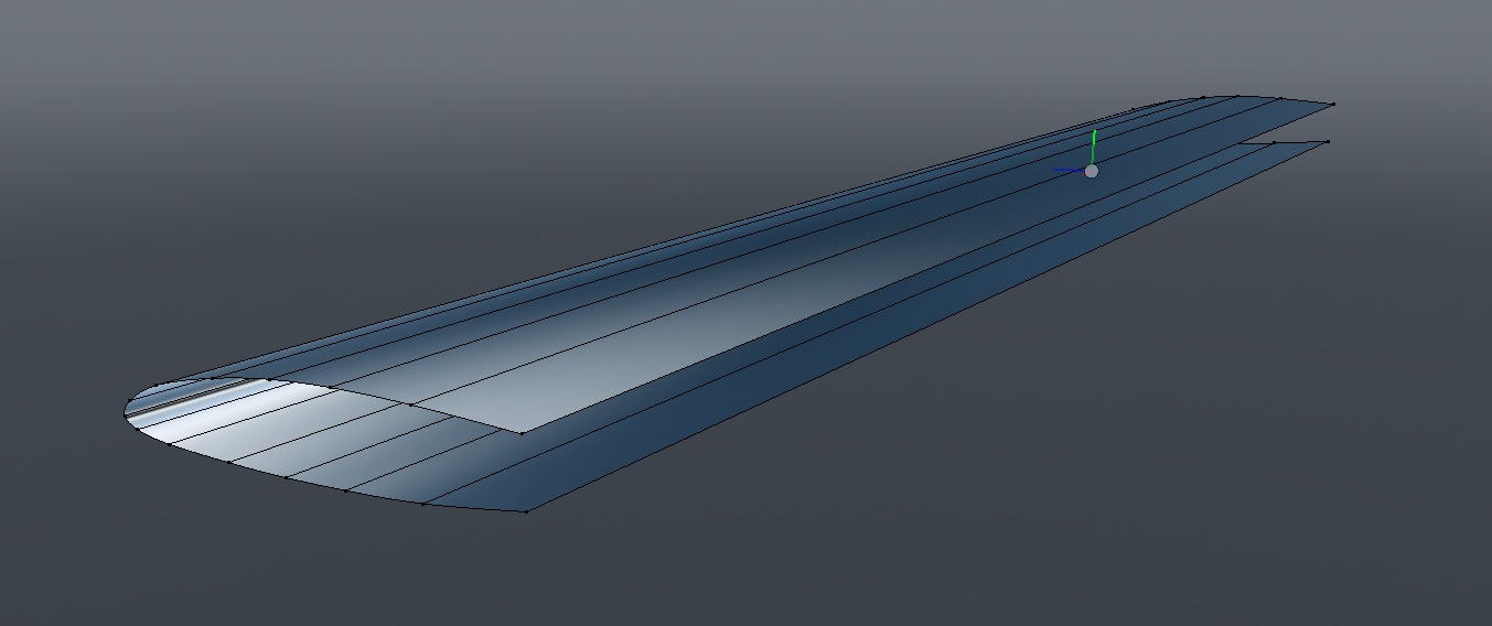
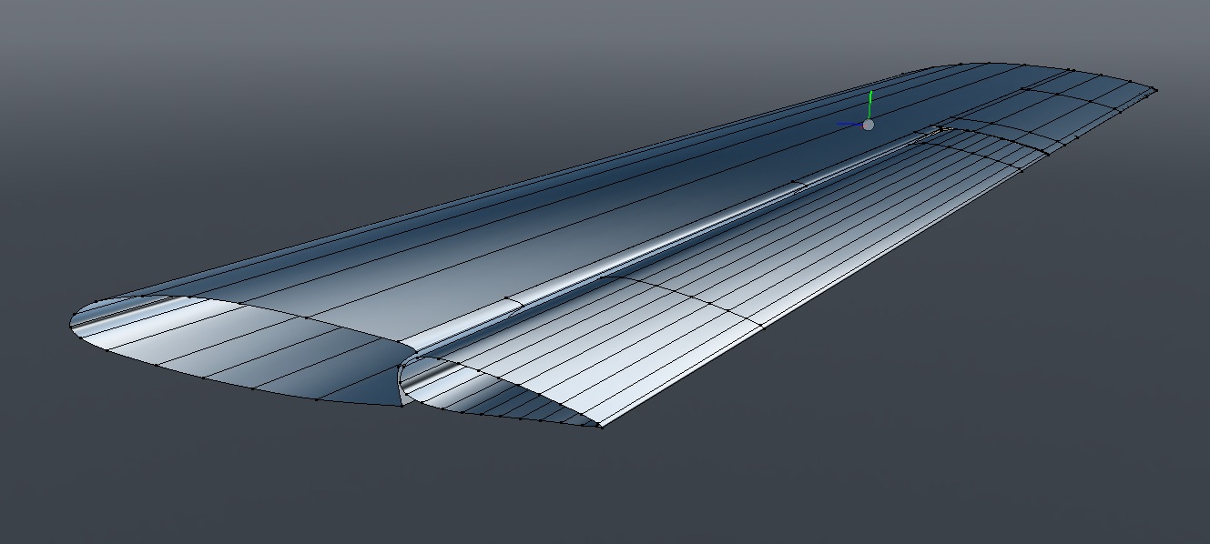
Generally, I would build the wing as one piece (like the vertical fin) and then slice it up. In the case of this aircraft, the wing has several distinctly-different sections, to accomodate both the outboard flaps, and the ailerons) so I began a little differently. This is wing section outboard of the engine nacelles, in it's most basic form.
First, the wing's airfoil shape, without the trailing edge.
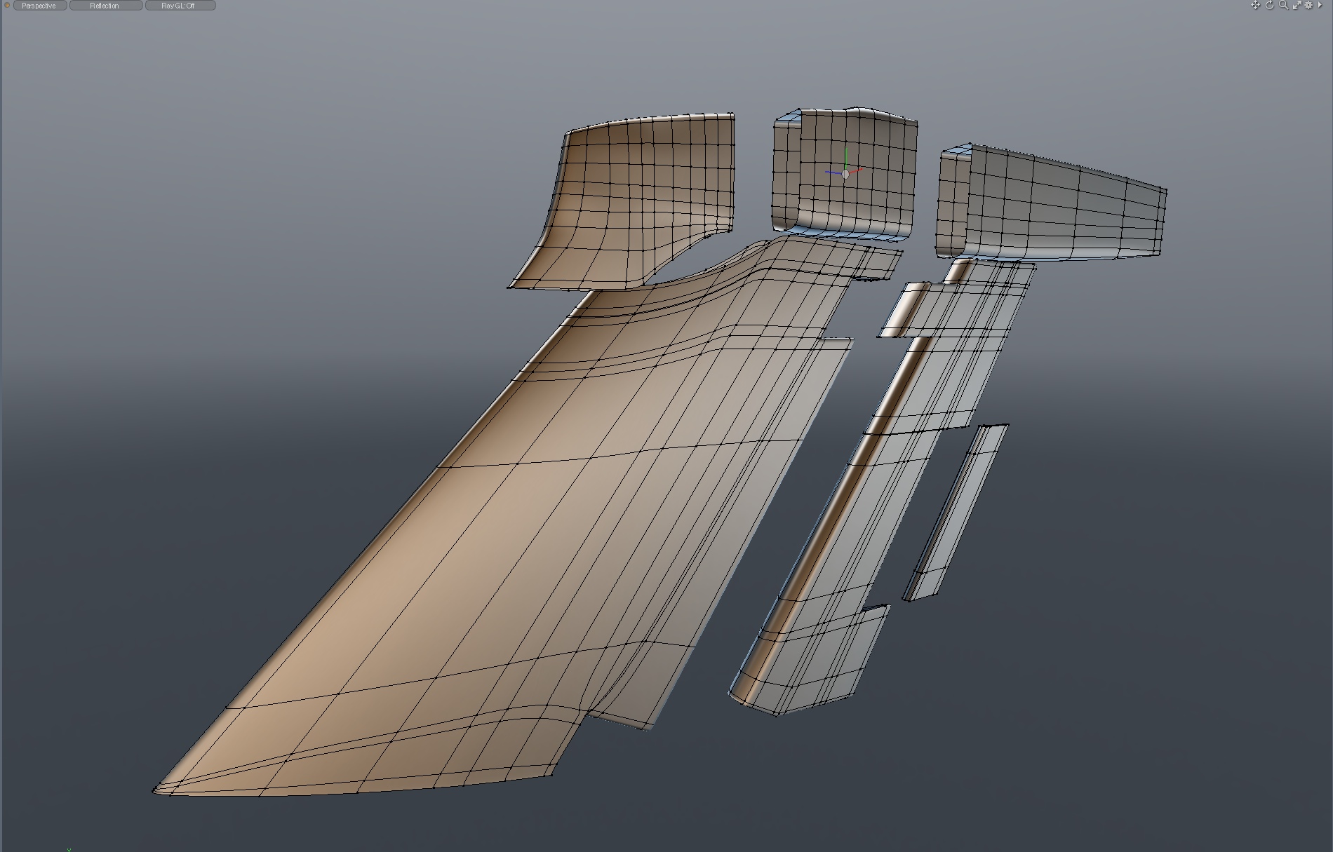
Since the trailing edges where the flaps are located is radically different than for the ailerons, I modeled those areas as separate parts.
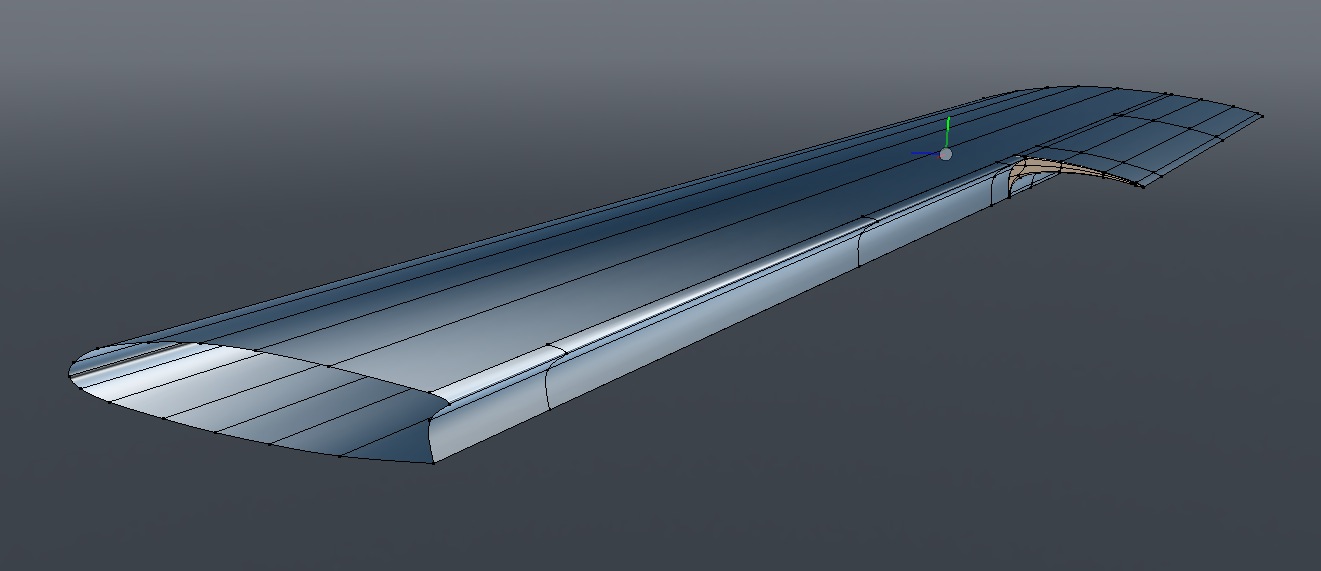
Next, the basic outboard flap shape was created.
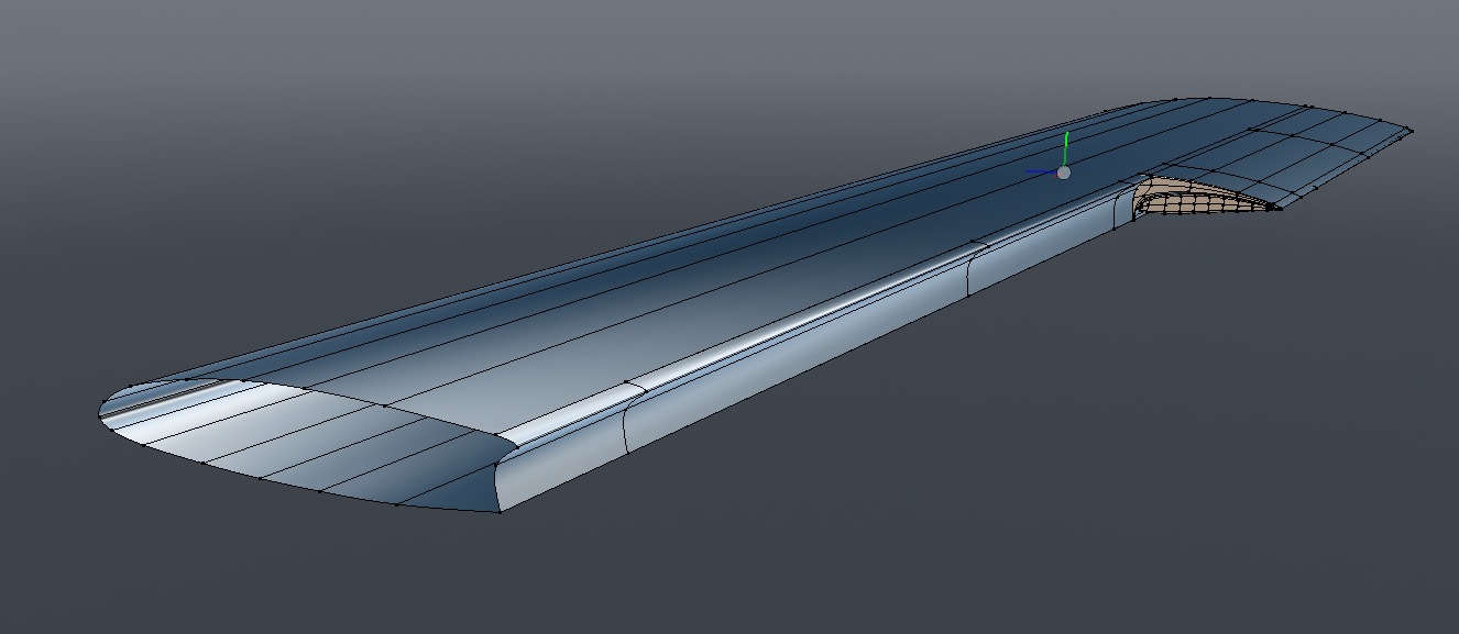
Finally, the basic shape of the ailerons was added.
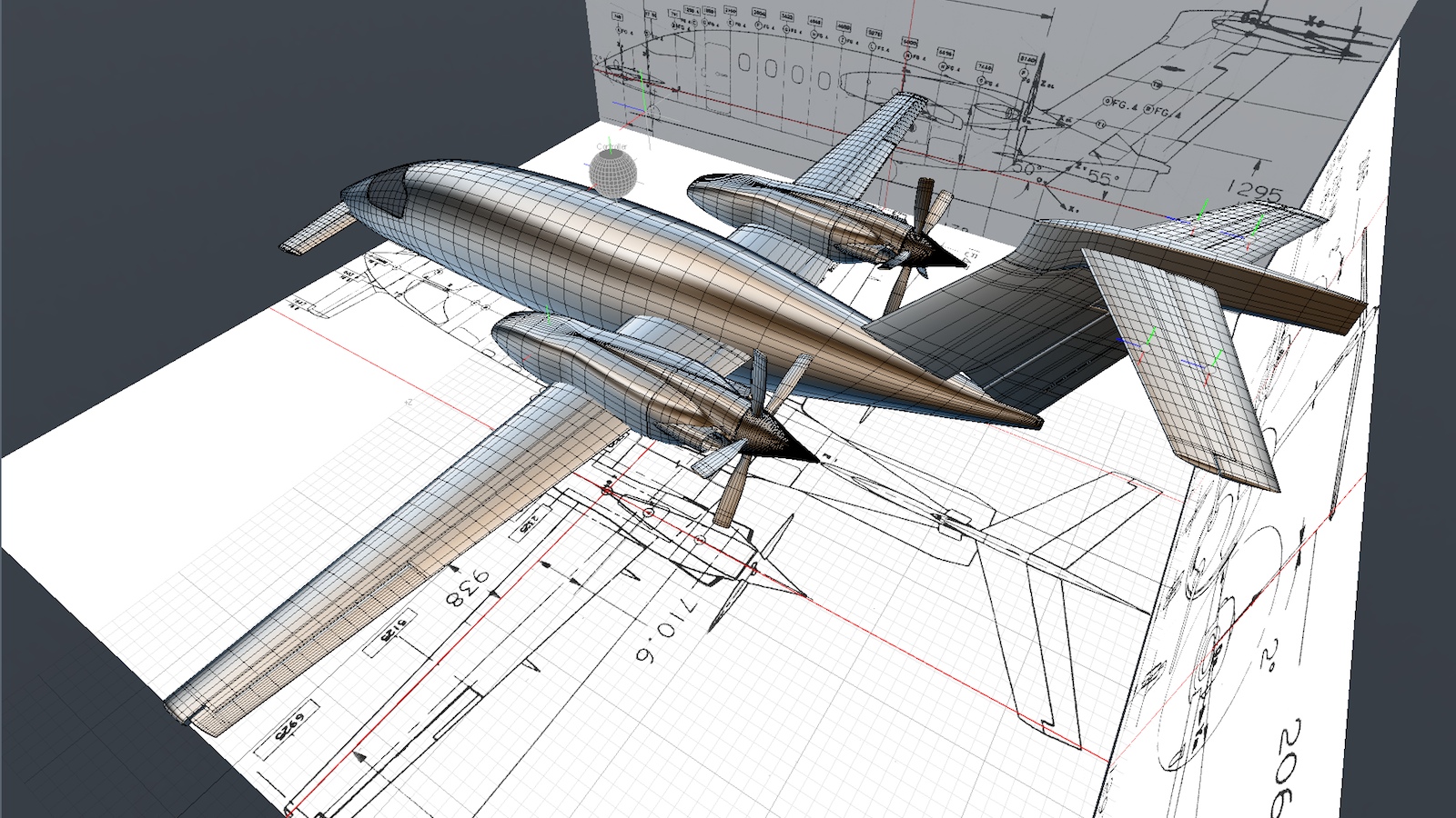
Next, I moved on to the foreplane, horizontal stabilizer and engine nacelles. I'm not showing the details of building those basic parts here, because it was the same as the previous steps. Here's the basic airframe assembled, which give us a good start for this model. Although these parts are simple, they are the most concrete reference I'd have to build the remaining structures, so I moved very slowly here, making sure each part was as accurate as I could make it. At this point, I'm using the propellers and propeller spinners from my previous model, as they're accurate. I'll replace them later with all-sub-d parts, but they serve well as stand-in geometry at this point.
Notice in the image above that I've also added quite a few edge loops to all of the parts. Like the fuselage, these were aligned with known station lines in the drawings. This serves several purposes. First, of all experience has shown that although accurate parts for something like a wing can built with elongated polygons along the X axis, sub-d surface generally smooth better, and are easier to connect to other parts, when the polygons are roughly a uniform size. These roughly equal-size polygons are helpful if we use MeshFusion, and they also export to other file formats with fewer tessellation problems. The other reason is that I'll be adding a lot of detail within these parts, (i.e window cutouts in the fuselage) so we'll need some more polygons to make that work.
Skin thickness:
It's wise to wait until the end of a project like this, before doing any thickening of these "skin" parts. During the course of creating the model, parts may be reshaped, and keeping them single-polygon surfaces makes this easier. And, not every part requires thickening. If the skin thickness will never be seen, there's no point in adding additional geometry.
Standards:
As you begin slicing up models like this, so that the seams on the model render in a way that looks like the actual aircraft, it pays to develop some standards. For example, it's likely that on the actual aircraft, most of the skin parts are the same thickness. So, as you model individual parts, establish some numbers that seem right to you (or can be documented) and use them uniformly throughout the model. That way, if you have to edit parts later, you'll find it much easier than you would if all these things were simply "eyeballed", resulting in many different thicknesses.
At the actual aircraft factory, parts are obviously pulled from "parts bins". So, to make your modeling process easier, develop your own preset library of these often-used parts, so you're not having to remodel things over and over. Typical examples are screws, rivets, nuts and bolts, but you may find other parts you can standardize too. This not only saves time, but reduces errors. Spend time modeling each often-used part very carefully, then you relax each time you use it in a new assembly. Here's where modeling at real-world scale is really helpful. If you can discover, perhaps via a maintenance manual, that a screw is 5mm in diameter, that's easy to model in MODO. It's much easier to use real-world measurements directly, rather than to try and model these at some random scale and convert them later. Your model will benefit by being much more accurate.
MODO allows you to easily customize your workspace, add custom pie menus and script/macro commands. Take advantage of that, when you find yourself repeating tasks over and over. For example, if you use the Edge Slice command with the same parameters over and over, it pays to create a macro and perhaps a hot key or pie menu to access it. Again, it's a way to keep things consistent and reduce errors.
Avoid Modeling Traps.
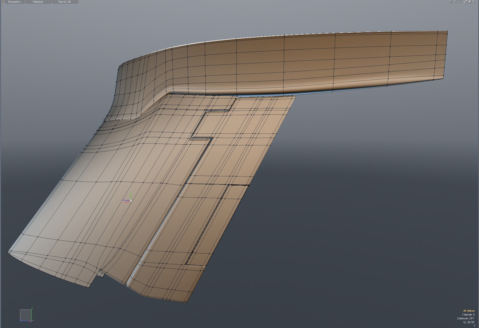
There are many ways to paint yourself into a corner on a project like this, and one tip that will save you some headaches later is to be careful with items that are ultimately placed at angles away from the normal X, Y, and Z axis. Below is one example.
Dihedral angle is the amount that wings or tail surfaces angle upward (when viewed from the front) and Anhedral angle is the amount that those surfaces angle downward. This aircraft includes surfaces with both.
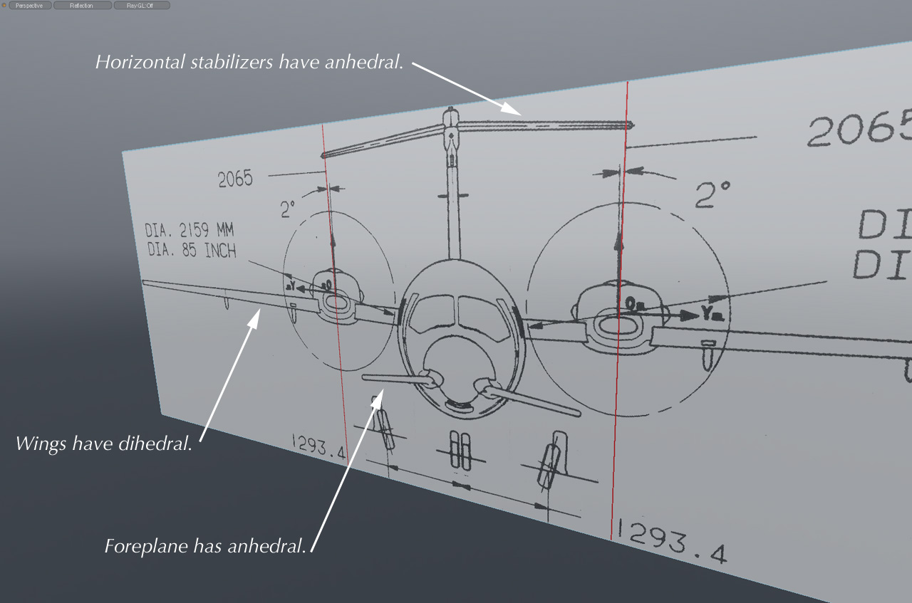
As with the vertical fin, we'll be cutting out various parts from the wings, foreplane, and tail surfaces. It's important to note that these are usually aligned with the item's actual axis. In other words, if you want to remove the ailerons from the wing, you'll find it easier to do with the wings level. So, my advice it to make all these cuts, install all the internal parts, add details, etc., before tilting them to their correct dihedral position. Or, you could place these things under a Group Locator in MODO, at zero degrees, and tilt them to their dihedral angle as a group. That's how I do it, because you never know when something will need to be added or modified. Whatever method you choose, just be aware of these things as you build parts, or you can find yourself in a spot where you're trying to realign the workplane for each part, or building them in place at these angles. It can be done, but is just simpler if the item is level.
Mid-Project Movie:
Here's a movie of the model as it stood on February 24th, 2014. (About 37 mb MP4 - Opens in a new tab)
Click the "Page 03" link below, to continue.