NOTE: I am not at liberty to redistribute the documentation used to build this model.
Cables, Pulleys, and Pushrods
Most images in this article are larger than what appears in your browser. To see any of them iin full resolution, just drag them to your desktop.
In case you missed it earlier, I posted a video showing the current animation rig for this model. (about 311 mb MP4) What you'll find below is a continuation of that process, connecting all the flight controls in the cockpit to their respective flying surfaces around the aircraft. Why bother with all of that? As long as I have the system resources, (and the patience) I'd like to make this model as realistic as possible. And, it's certainly interesting and challenging
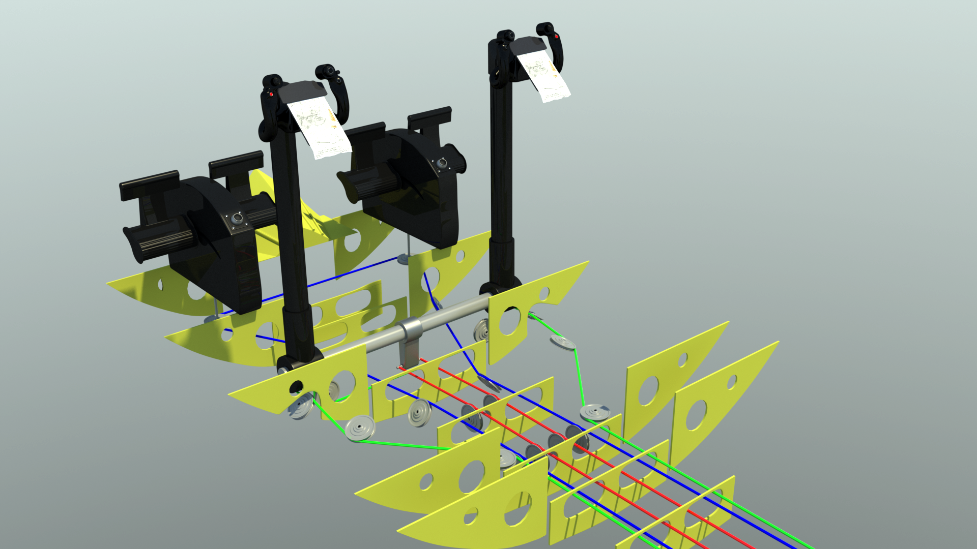
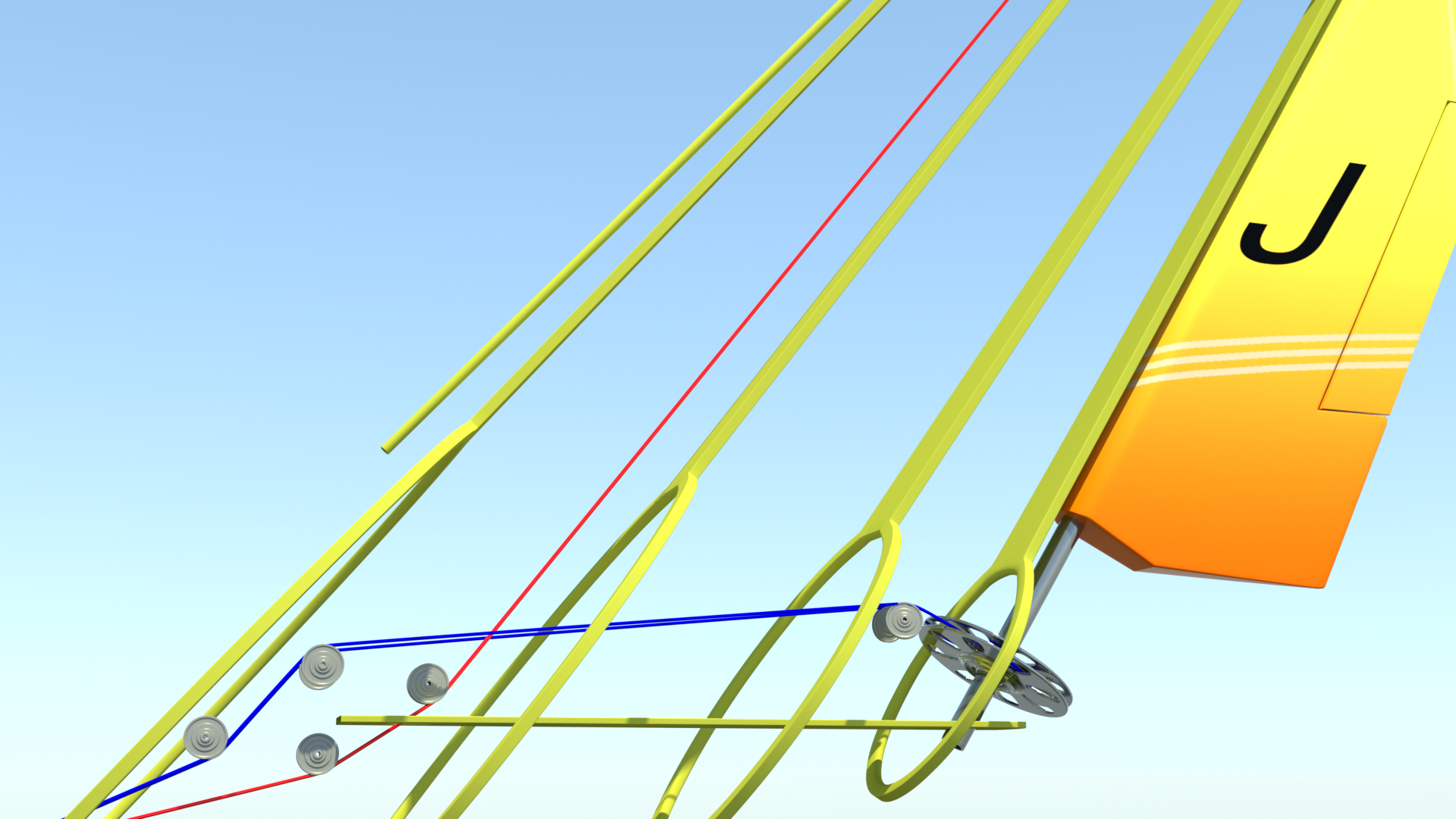
I used MODO's "renderable curves" to produce the control cables, because they're easy to edit, and can be animated later. For now, I've color-coded all of them, to help me keep track of where they're going. Elevator cables are RED, rudder cables are BLUE, and aileron cables are GREEN. In the cockpit area, some of the cables create the interconnect between the pilot and copilot control columns and rudder pedals, before running aft to the flying surfaces.
I have some basic system drawings that give me a pretty good idea of where all the cables and pulleys go, so I decided to start with the setup you see in the first couple of images, and then, using the existing structure to help me, rearrange specific components as needed, to avoid interference issues. When I'm satisfied that everything is in the right place, I'll go back and add the mounts for the individual pulleys.
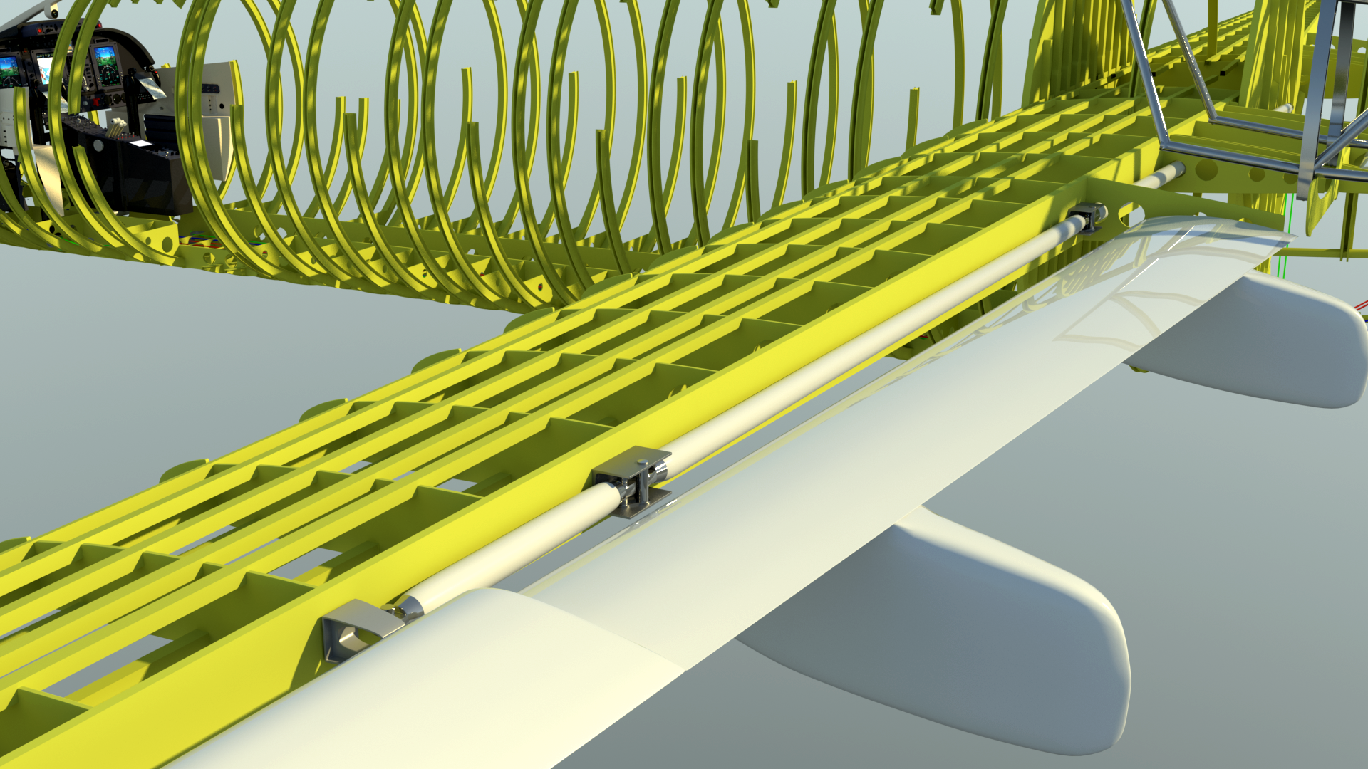
For those of you with an eye for detail: You may notice that in some of the wing renders below, that the wing's stringers are not flush with the tops of the wing ribs. That's not an error, just the result of me working on connections to the spars, rotated slightly to zero out the dihedral. Since it didn't matter, I left the stringers in their original positions, with the dihedral)
Everything starts in the cockpit.
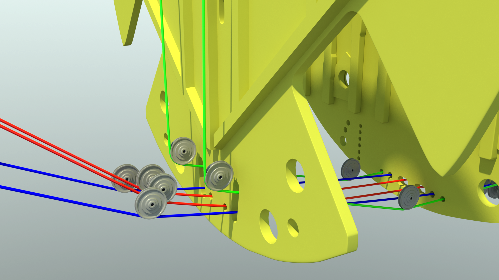
Now you can see why I cut all of those holes in the major bulkheads. Some holes are for the control cables, and some are for electrical, hydraulic, or fuel lines.
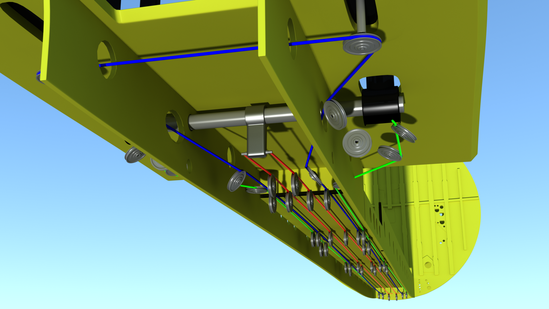
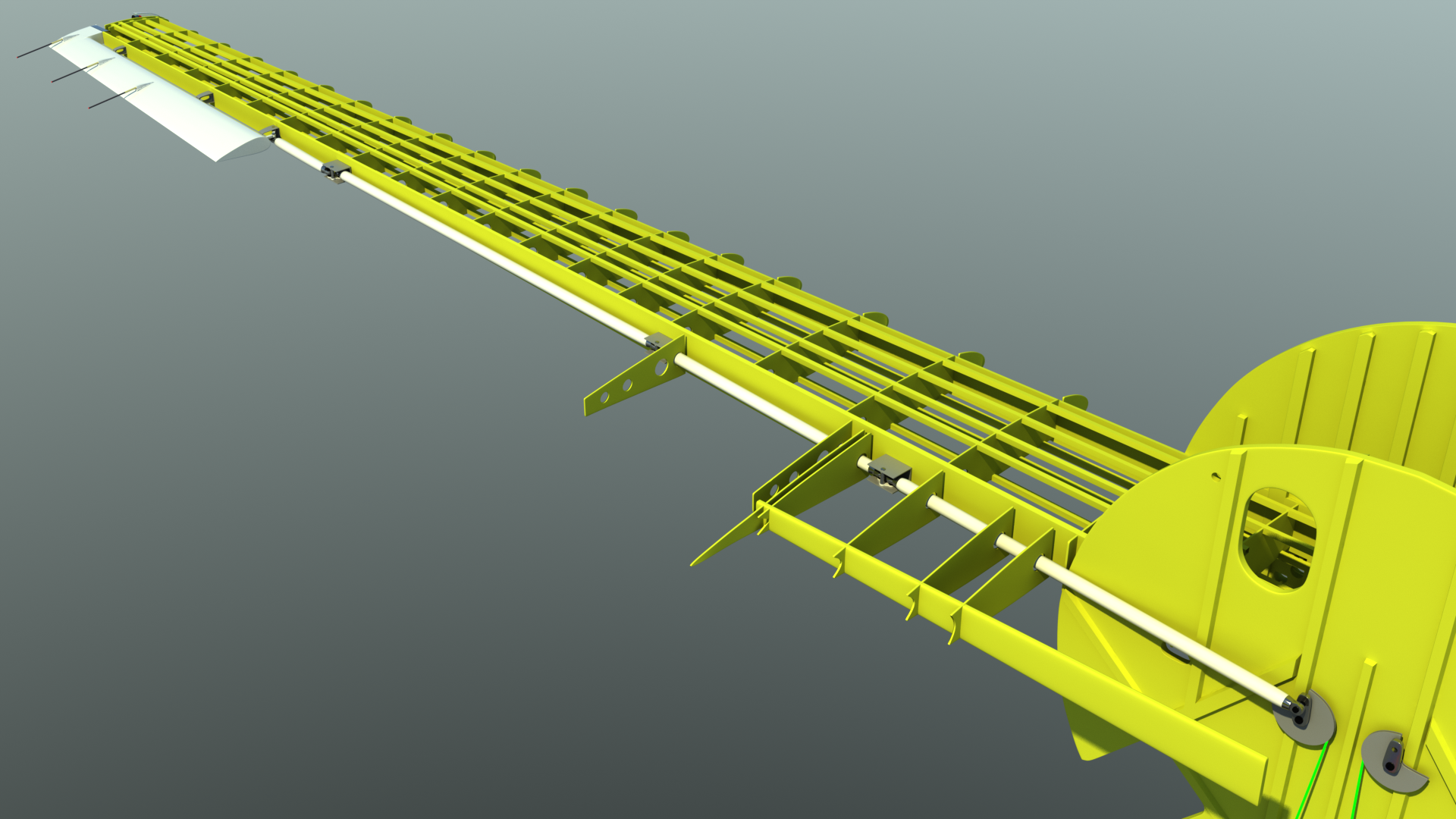
The ailerons use a push-pull system of rigid pushrods and bellcranks, running along the aft wing spar.
Here are the aileron cables, routed upward to two large bellcranks, connected to the pushrods mentioned above.
The rudder pedals are adjustable, forward and aft, which is why the opening in the cockpit floor is rather long. Here, I've made some adjustments to those cables' positions.
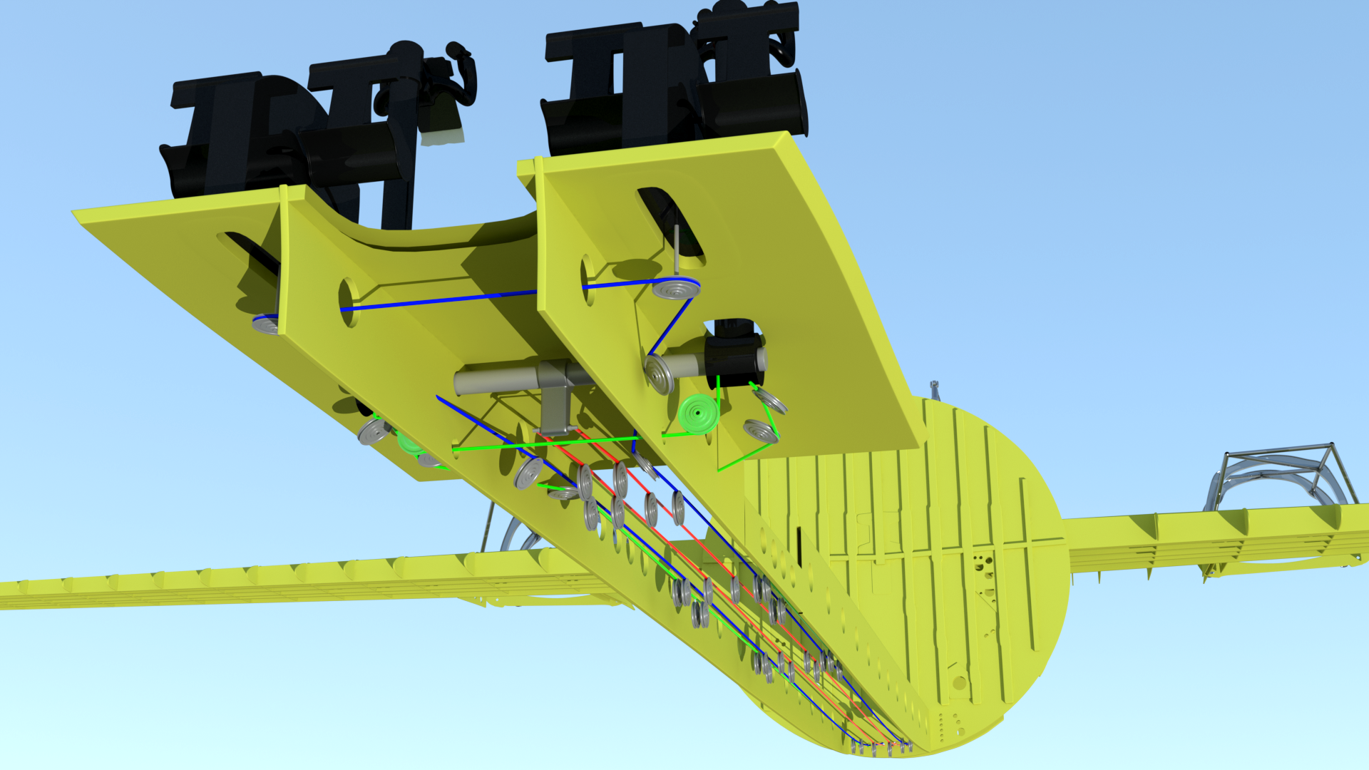
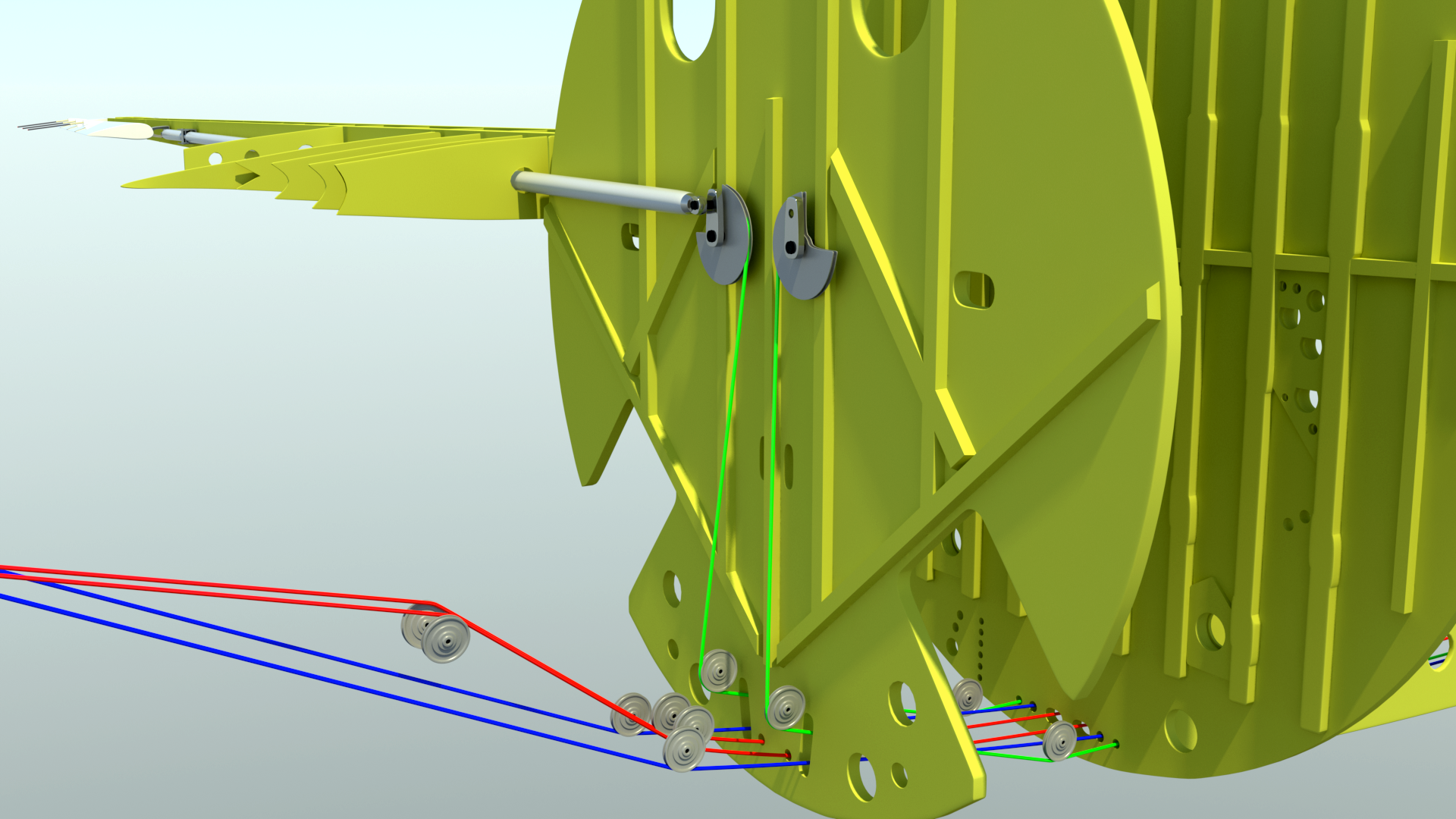
The (red) elevator cables running up to the T-tail, and the (blue) rudder cables running to the large control horn at the rudder's base, where they loop around it.
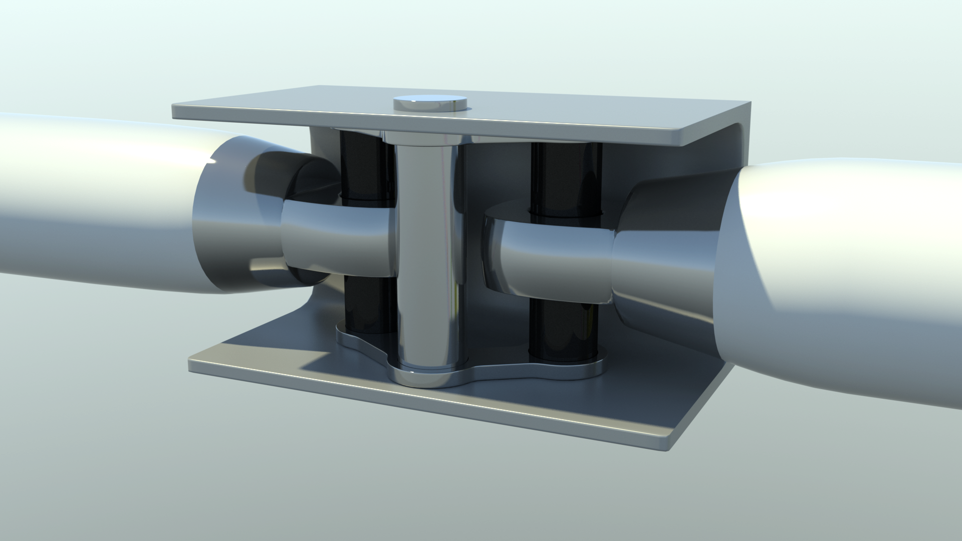
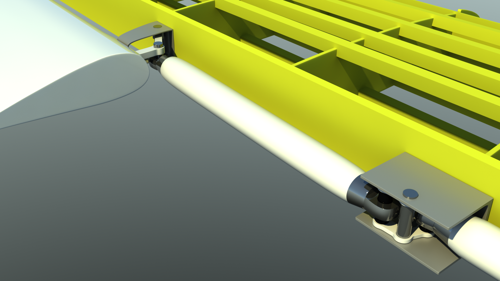
A closeup of one of the many aileron pushrod connections.
Looking aft from under the cockpit, you can see how cables interconnect the pilot and copilot, then route to the center of the airframe before passing to the rear of the aircraft.
Next two images... More work on the aileron pushrod system.
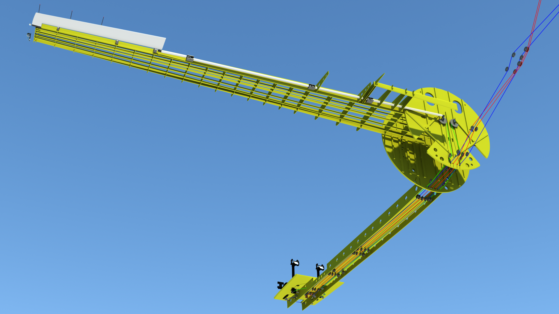
Overall view from under the aircraft.
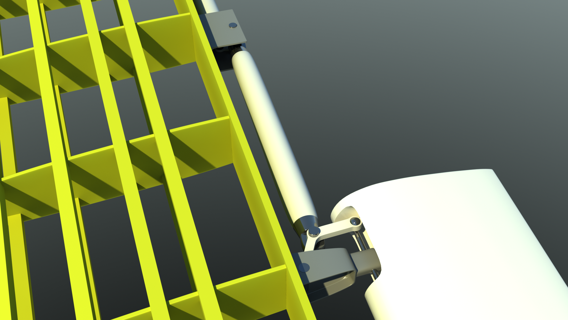
The outboard bellcrank connection to the ailerons
Transparent views to check for interference issues... Everything fits!
After installing all the above items, there were a few interference issues to solve. For now, I've left the cables color-coded, for easy reference. Later, I'll change all of them to a steel color. The existing structures showed me where a few of the pulleys and connections had to be moved to, and I've got them all fixed now. Next, I'll do the electrical, hydraulic, and fuel lines, which will be done in a similar way.
(In these views, the slightly darker green color in the wings indicates where the wing fuel tanks are.)
More control systems, engine mount improved, and radar added:
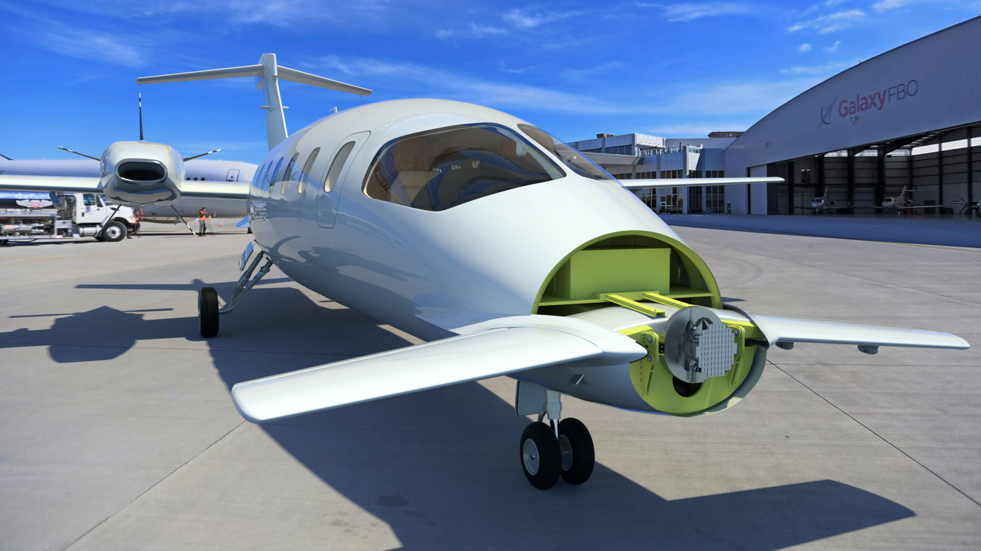
Obviously, I can't add every single nut and bolt that appears on the actual aircraft. But, some things are visible at longer range, and I add those as I keep looking at the model. The first thing I've added here is the hardware that connects the foreplane to the nose. The two black boxes installed outboard in the foreplane are (animated) servos, which lower and raise the foreplane flaps.
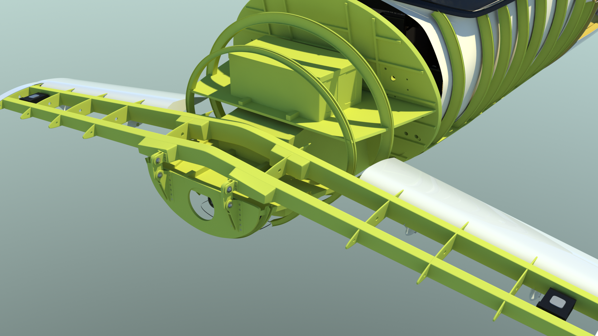
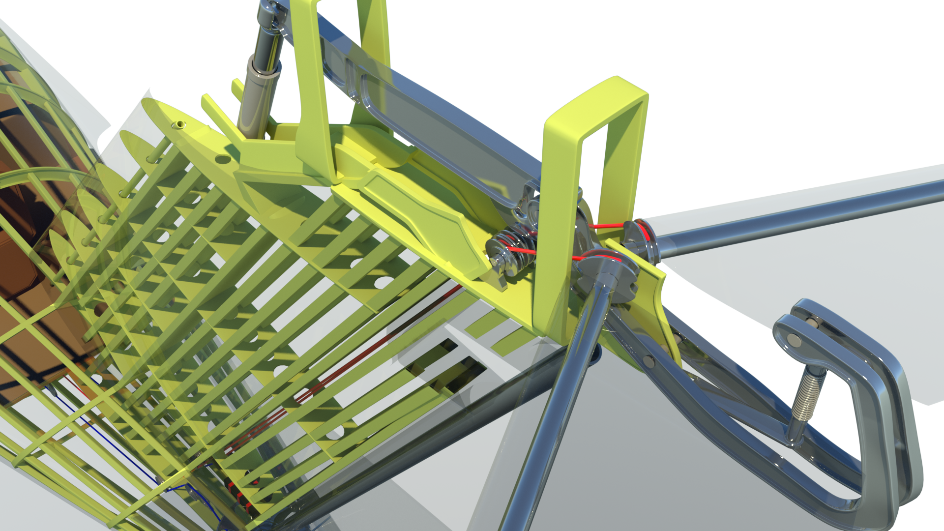
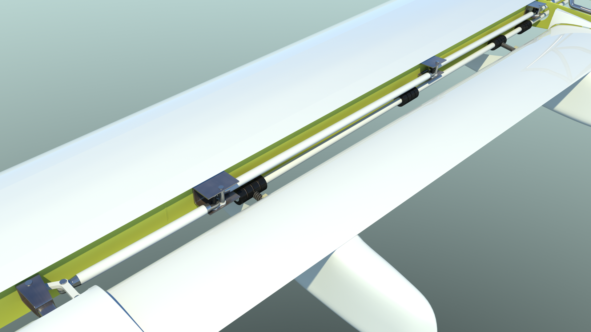
The cables and pulleys, hydraulic trim actuator, and the centering spring mechanism added to the horizontal stabilizer system.
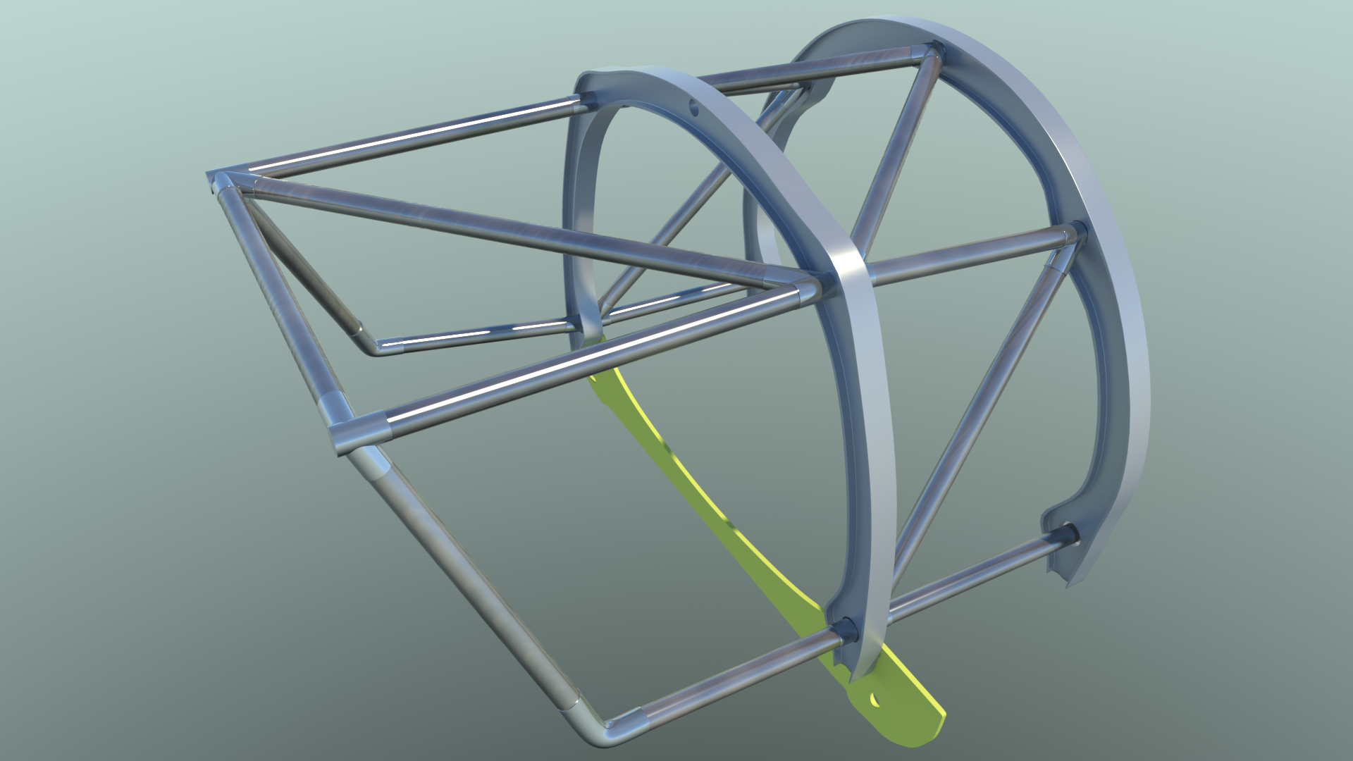
Finally satisfied that the tubes are in the right positions, I've added the caps at each tube junction, so that the engine mount looks more realistic.
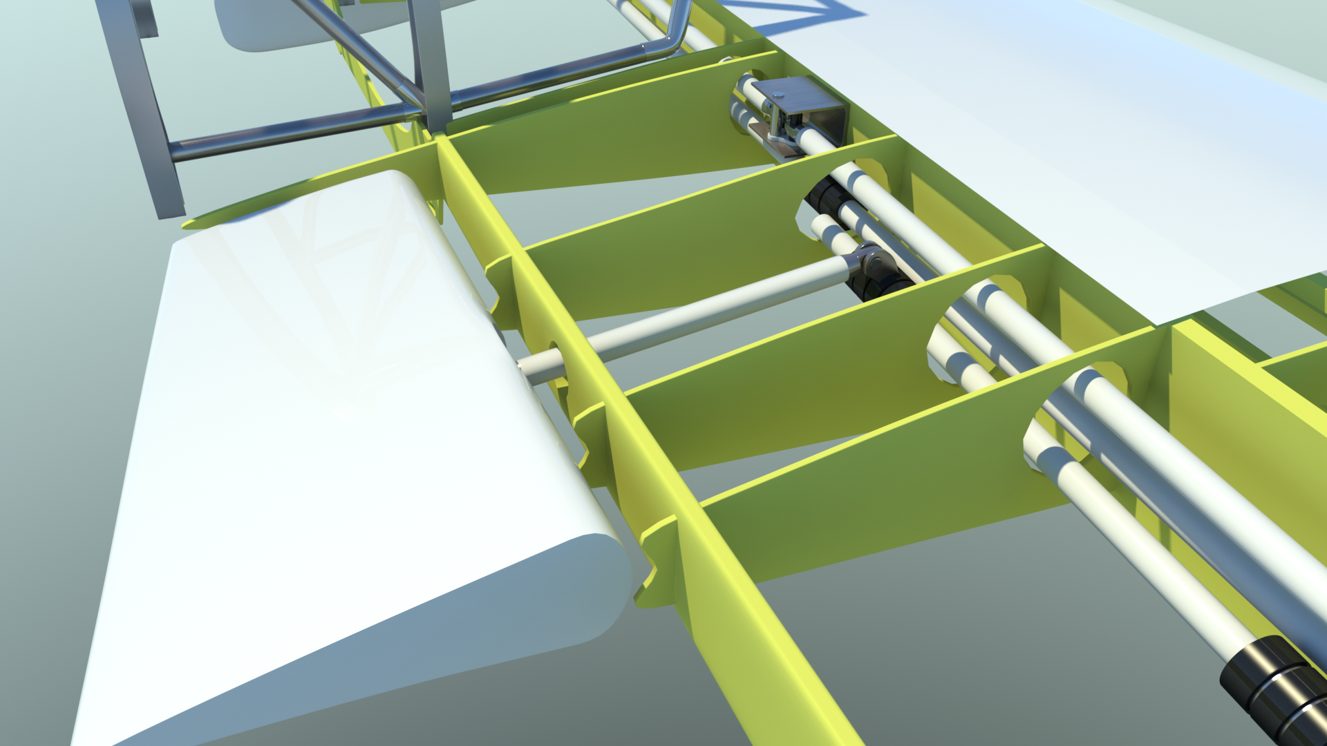
The next two renders show the mechanical linkages for the inboard flaps (pushrod and bellcrank) and the outboard flaps. (rotary shafts driving two jackscrews. These jackscrews on the model actually turn when the flaps are raised and lowered.
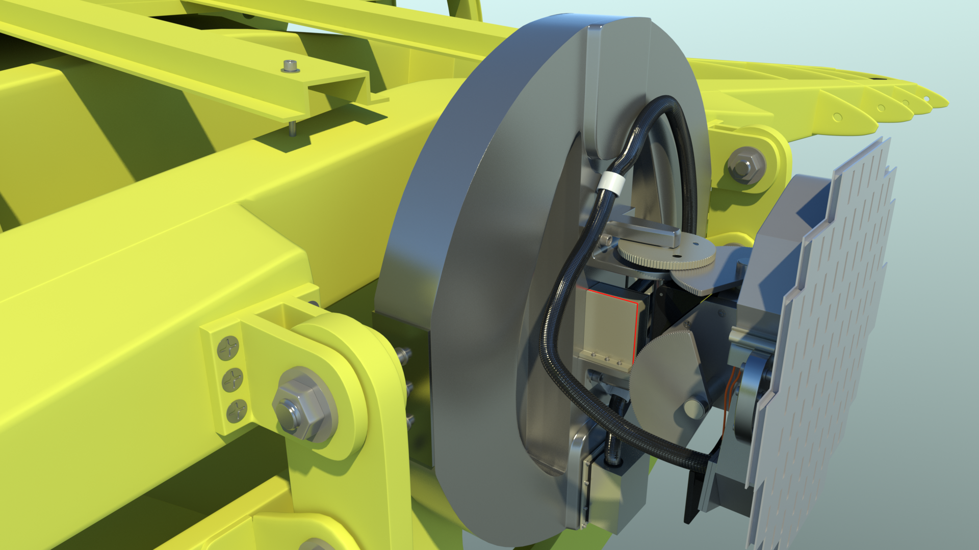
Next the Rockwell-Collins weather radar in the nose. The radar on the model is animated, showing both the left/right sweep, and the adjustable up/down tilt.
Depending on what's visible at render time, this model is typically rendering at about 39 million polygons, with all Catmull-Clark surfaces, at a subdivision level of "2".
Update Videos:
Rigging update: Click here for the latest video update, as of October 7th, 2014. (about 205mb MP4)
Model overview: Click here for the latest overview, as of November 3rd, 2014. (about 127mb MP4)
To continue, click the "Page 07" link below.