- Page 01
- Page 02
- Page 03
- Page 04
- Page 05
- Page 06
- Page 07
- Page 08
- Page 09
- Page 10
- Page 11
- Page 12
- Page 13
- Page 14
- Page 15
Cessna T-50 "Bobcat" - The final exterior shape
* Most images on this page are larger than they display here, in case you'd like to download or print them.
The fuselage
For a while now, I've simply been posting images, showing the model's progress. Some of you might be interested in this part of the process though, as it involves combining several kinds of documentation, to get the best results. It also shows some items in the 3D model that you don't normally see in the renderings, because they're to small.
For those of you not familiar with this aircraft, most of it is covered with fabric. This fabric isn't just wrapped around the tubing structure, though. There are many small wooden formers that attach to the outside of the tubing, and it's those which give the fuselage it's actual final shape. My approach for this step is to use a combination of Cessna drawings and photos to end up with the same thing, in scale. Here's how...
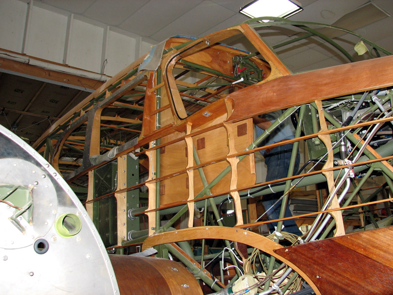 Have a look at this photo of an actual T-50 restoration. You can see all the formers I was referring to, which give the aircraft it's shape. Since it's impossible to get complete measurements of each one of these, (and they're all different) another method had to be used, and it's one I've used often on many projects in the past, with good results. I would describe t as "the plane taught me". (meaning that if you have "A" and "C", it's sometimes possible to find "B".
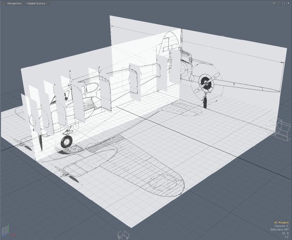 Here's a pretty typical setup for reference materials, in a 3D program. It takes a little PhotoShop time to get all the images cropped and scaled to match, but it's well worth the effort. The cross section drawings were used as another way to verify the 3-views, as well as the aircraft shape.
 Since I've already created most of the items on these drawings, I usually leave them turned off. But, after a long modeling session, I often check the model against them again, just to make sure that nothing has gotten out of whack.
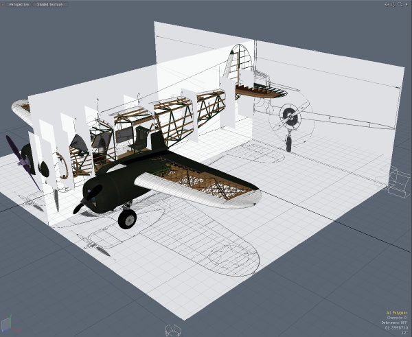
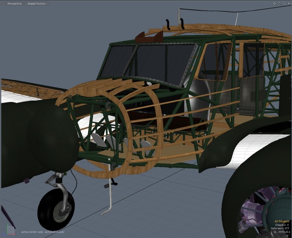
In this case, the focus isn't on the overall shape of the aircraft, but on the individual cross sections.
 I'm installing the wooden stringers to match the cross section drawings. Knowing that the tubing structure is accurate, and having the photos in hand (about 450 right now) allows me to figure out the shape of the former that goes in between those stringers and the tubing structure.
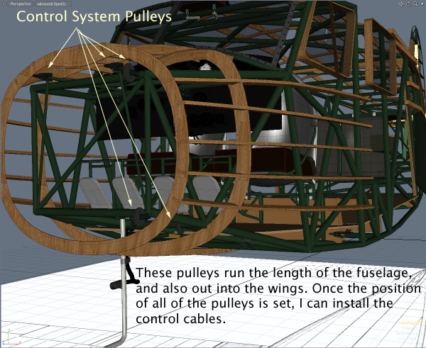 There are a number of pulleys around the fuselage, and in the wings, which go from the cockpit to the control surfaces. When I'm convinced that the pulleys are in the right places, I'll add the control cables. It should be a challenge, and make the model look more realistic, too. It's a prerequisite anyway, if I'm going to install some of the visible wiring, etc.. (The cables must have clearance.)
 Control cables for the ailerons are routed through the leading edge of the wing, and then to this bellcrank assembly, just in front of the ailerons.
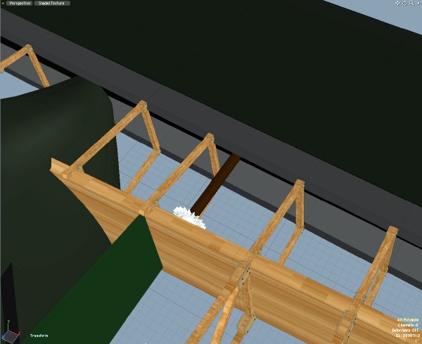
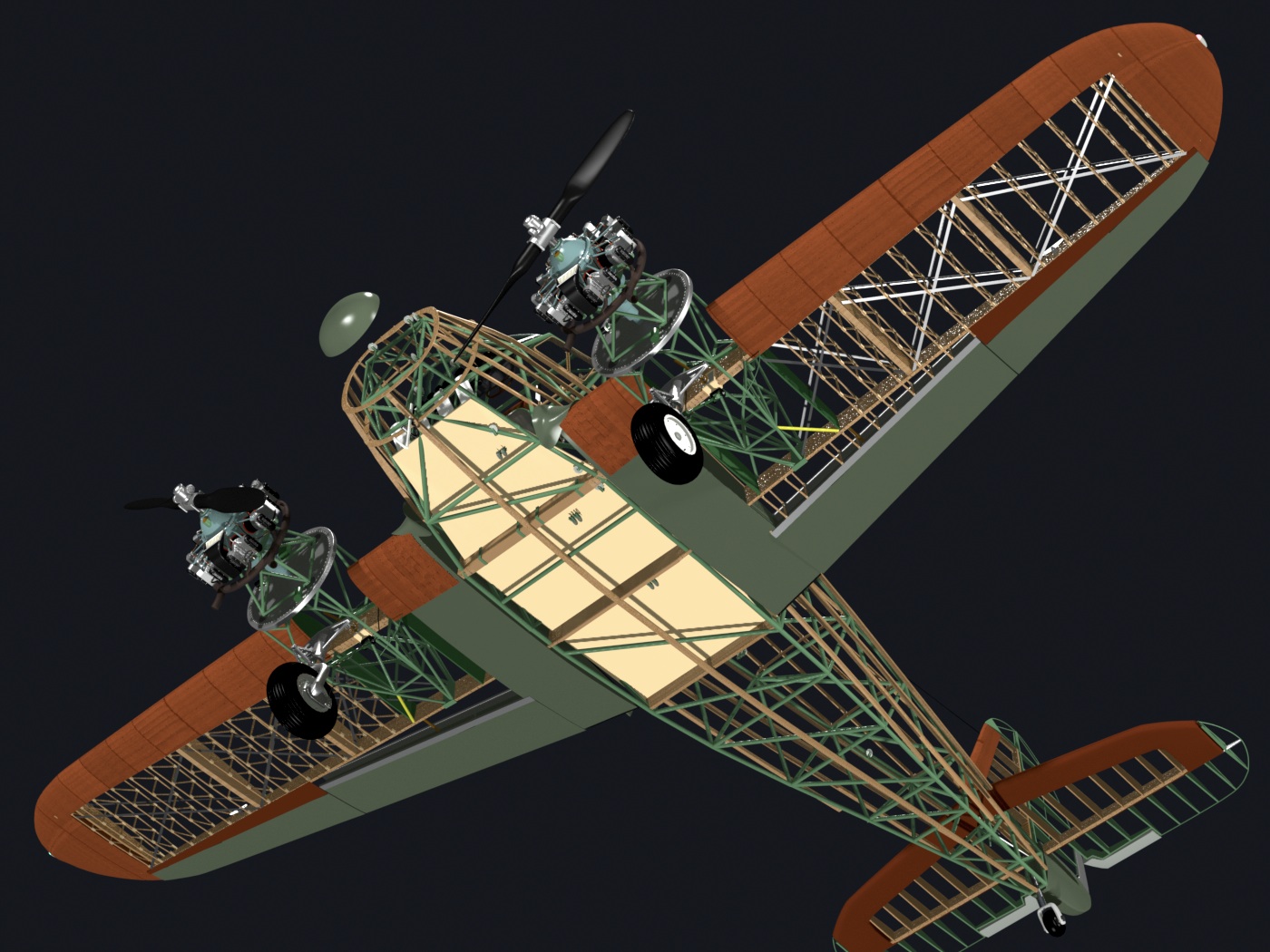
Re-checking these things often also shows where I have some interference issues, such as with these wing-bracing "wires". (the black strips in the image) On the actual aircraft, some of the ribs were modified to account for that, so that editing is ongoing. The close-ups also show the occasional issue with textures. Here, you can see the the wood texture toward the center of the image is out of whack. (fixed later)
 The flaps are electrically operated, with the same kind of jackscrew used for the landing gear. Both use a chain drive system.
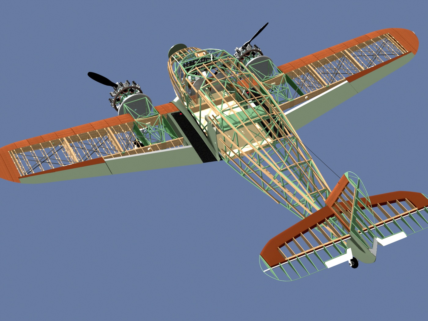
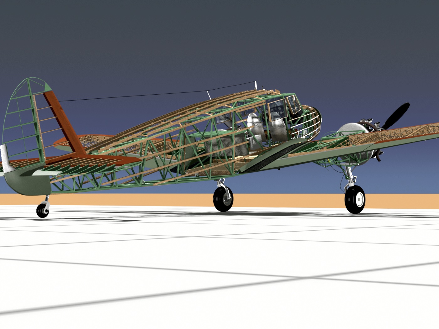
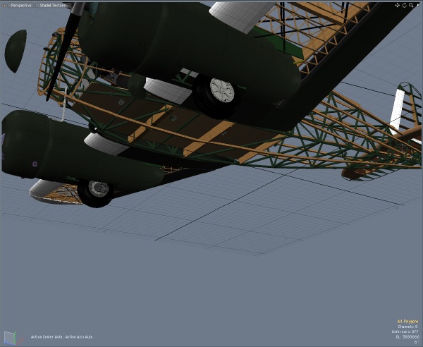 At some point, I'll either render the model in flight, and/or just want to animate the landing gear, so I've been working on that, too. Here it is, in the retracted position. On the real aircraft, the landing gear protruding down like that made it possible to reduce damage in a forced landing.
 When all the wood parts are in place, I can then use the exterior stringers as the way to "attach the fabric", just like the actual aircraft.
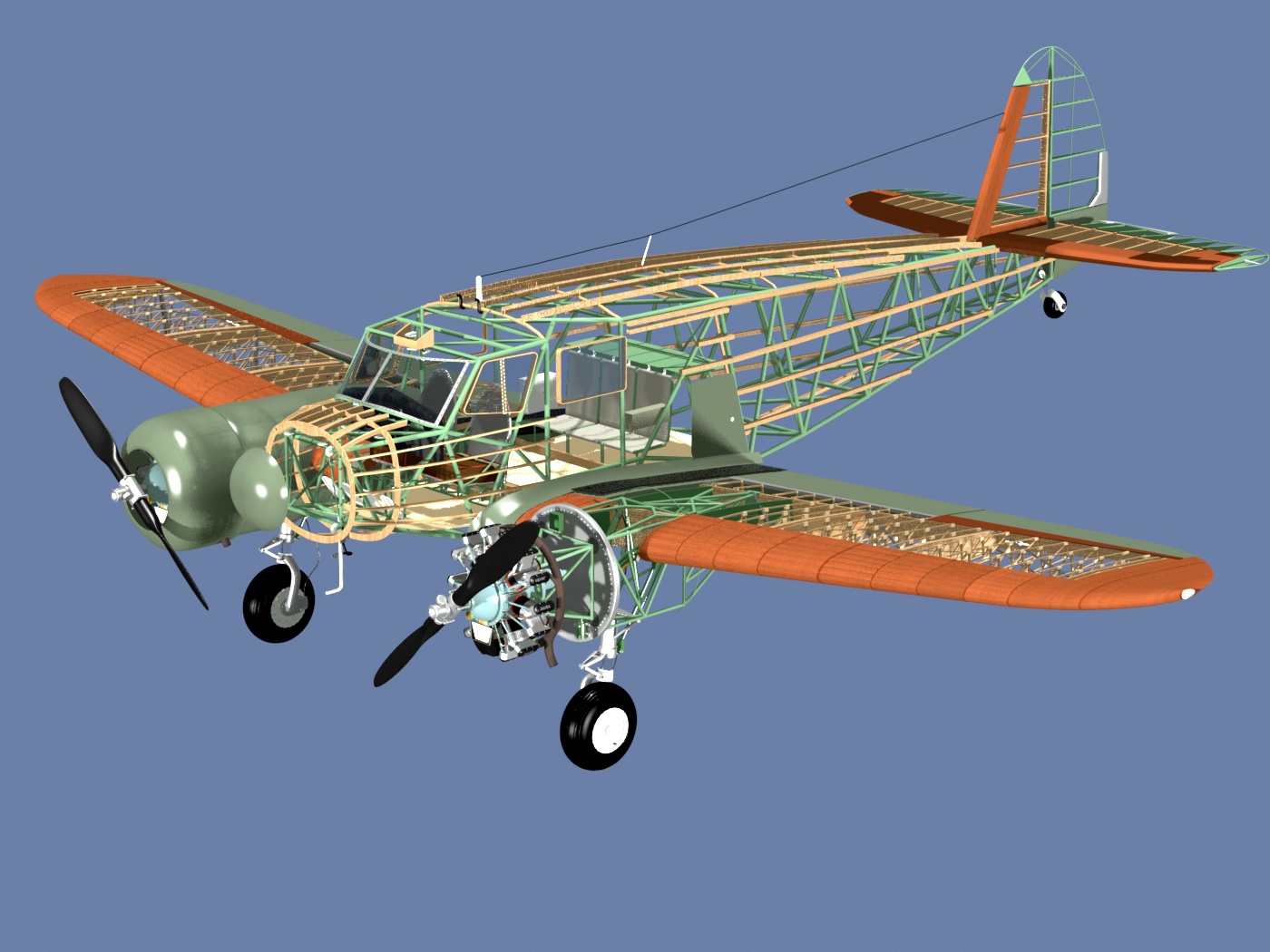
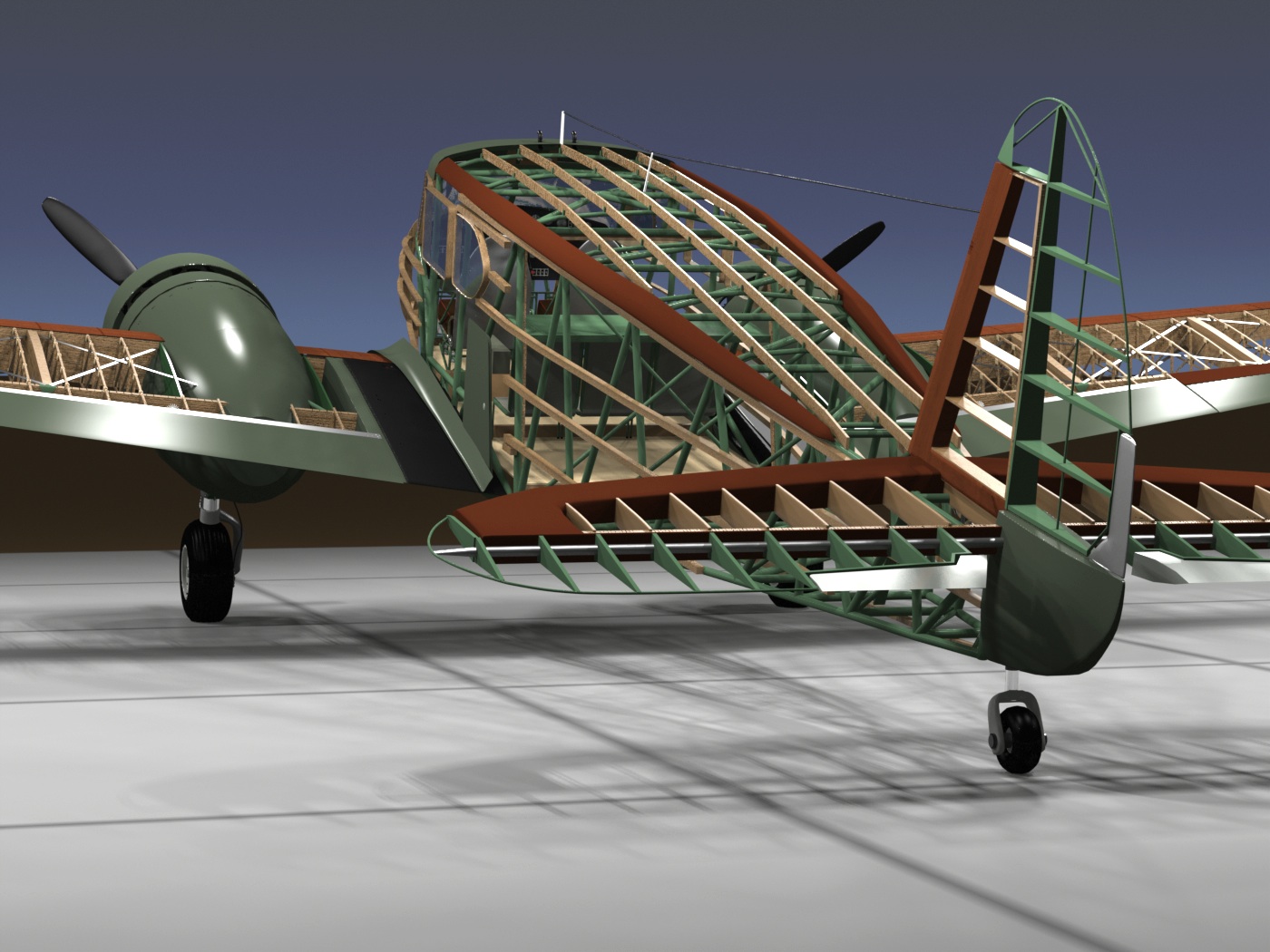
Some new renderings...
The newest items, in case you want to look for them in these renderings, are:
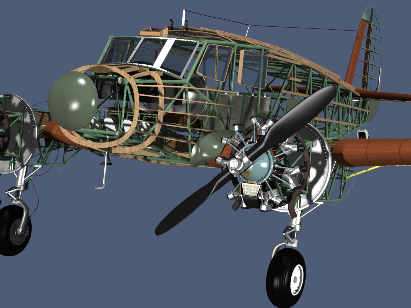
- Air intakes and filters on the engines
- Fuselage/Wing fairing created
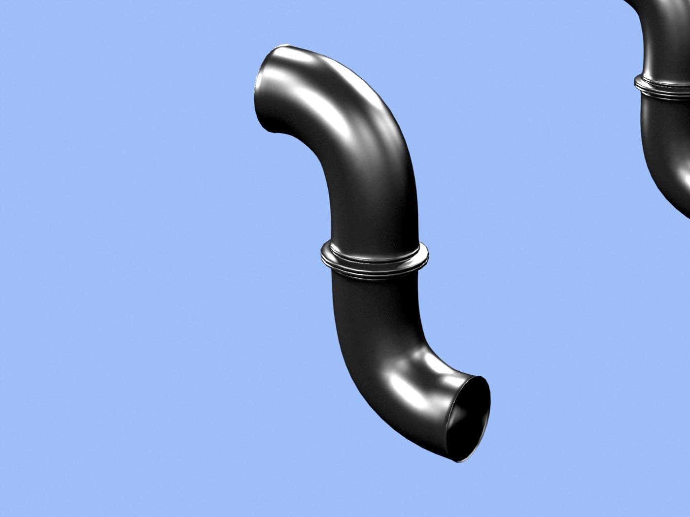
- Engine exhaust manifold refined
- Propellers are new, and more to scale
- The interior of the horizontal and vertical fins is all new.
- All the wooden stringers, discussed above
- Positioning of the known pulleys, and the control surface linkages
The control system...
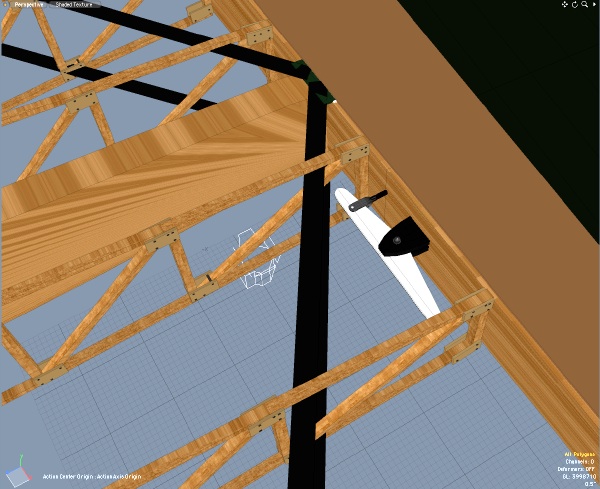
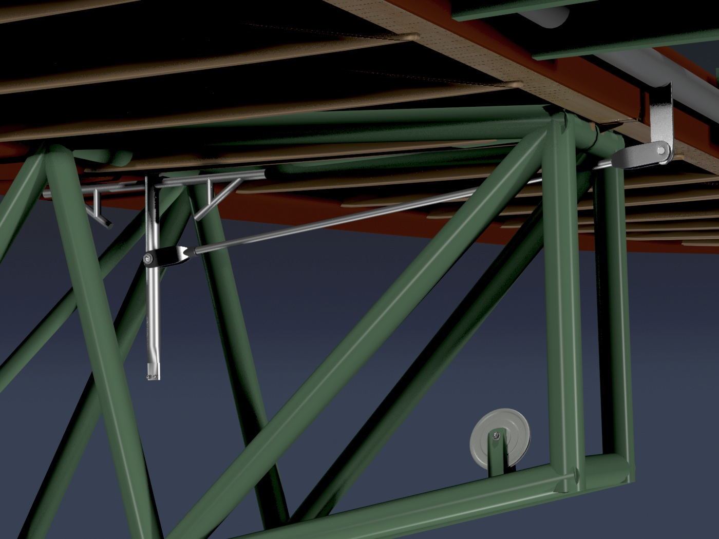
Th image below is the linkage for the elevator, at the tail. The T-shaped assembly at the top is the bearing that allows the pipe below it to move. Not shown yet, but installed on the two side pieces, will be two springs, which provide a tensioning/centering system for the elevator. The elevator cable makes a loop through the pulley at the bottom and is physically connected to the spring-tensioned pipe, transferring motion through the pushrod, to the elevator horn at the rear.
Other details...
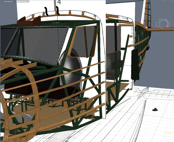
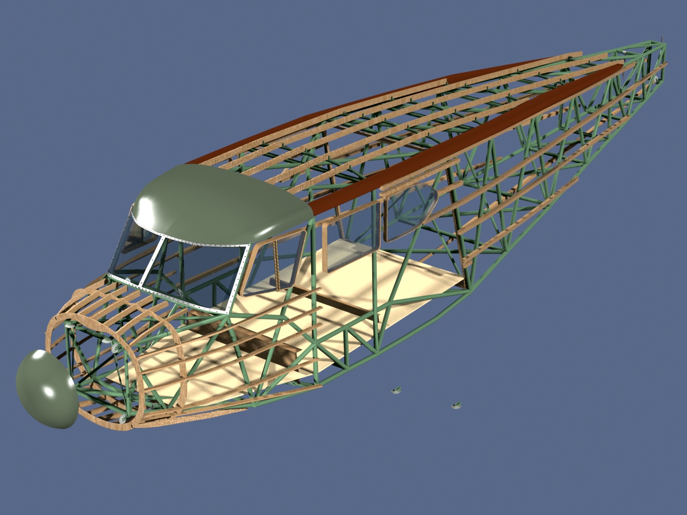
The covering shown here over the cockpit roof is not an actual part on the airplane. It's just a "skin" I'm using in 3D, to create the final top frame shape. This stand-in part assures that the final surface will be the correct curvature.
The "periscopes"...
These are close-ups of the overhead cockpit vents. Very simple engineering, as pointed out to me by Terry Sullivan. Turn them into the wind for air... Turn them away from the wind, and they create a suction, venting the cabin.
Still have to add some lightening holes to the tail ribs, but otherwise, it's looking good.
Click the "Page 12" link below, to continue.
- Page 01
- Page 02
- Page 03
- Page 04
- Page 05
- Page 06
- Page 07
- Page 08
- Page 09
- Page 10
- Page 11
- Page 12
- Page 13
- Page 14
- Page 15