- Page 01
- Page 02
- Page 03
- Page 04
- Page 05
- Page 06
- Page 07
- Page 08
- Page 09
- Page 10
- Page 11
- Page 12
- Page 13
- Page 14
- Page 15
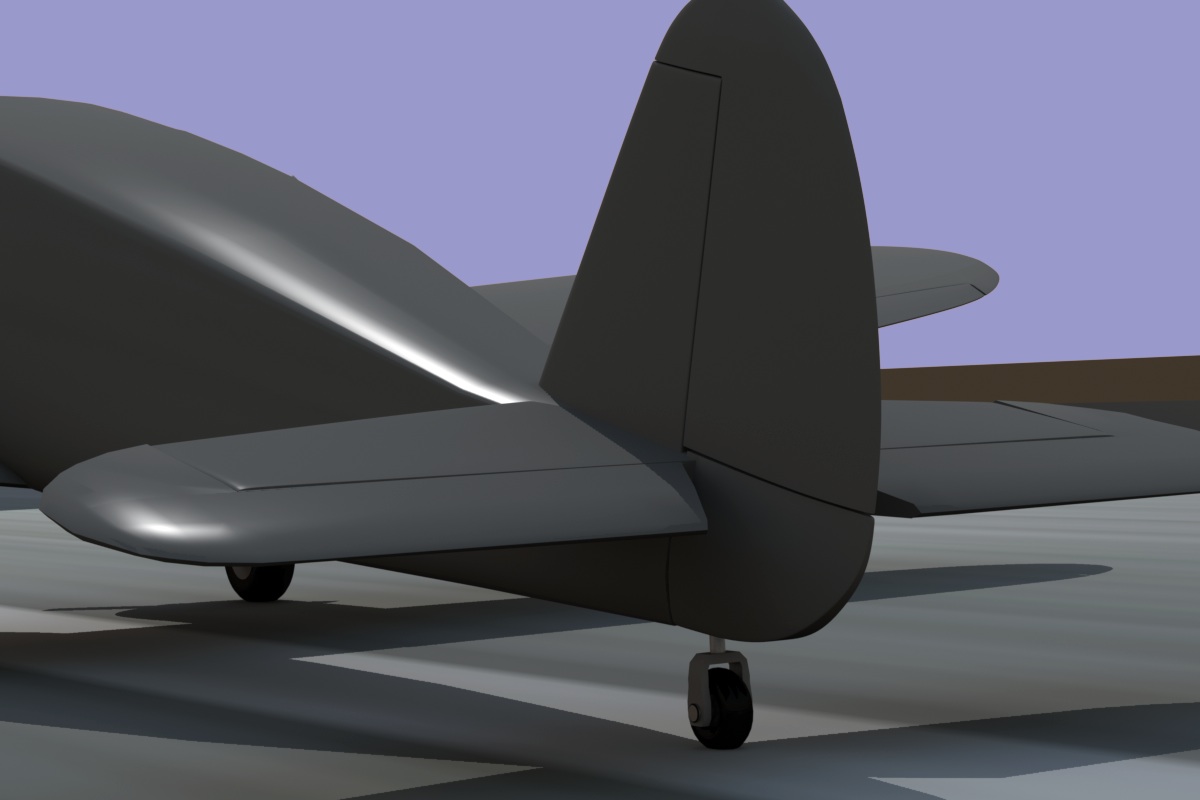
Cessna T-50 "Bobcat" - First things first... I fixed the Vertical fin/Rudder shape.
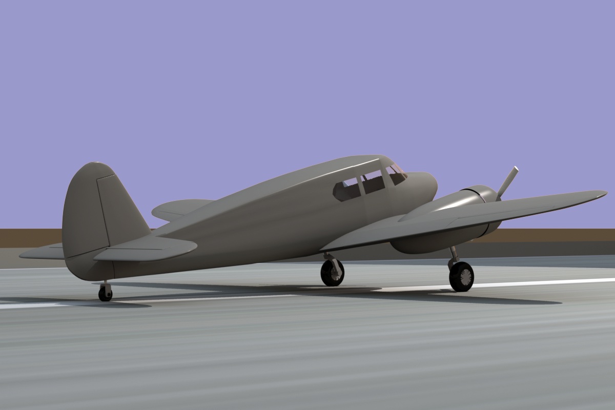
Other work on the tail parts includes making of the "tail cone", which houses the tail wheel mounting bracket. I also added the tail wheel strut and bracket, and thinned the tail parts.
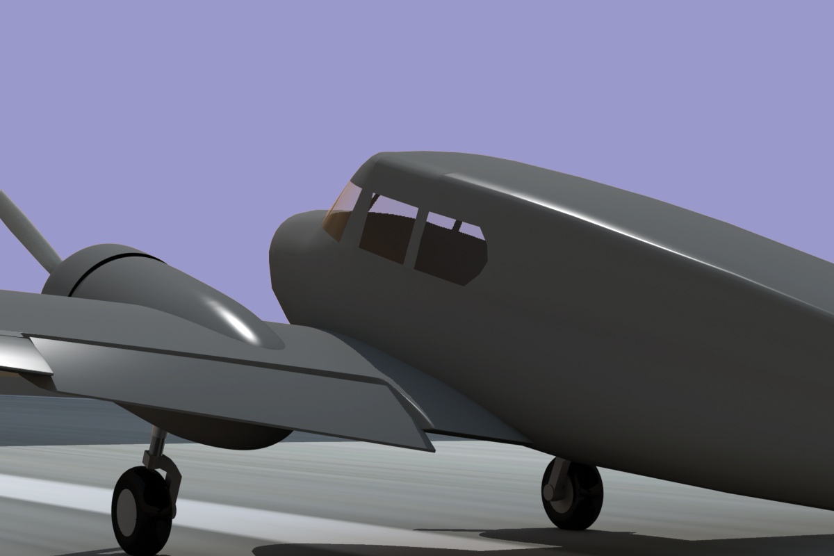
The nose area has been tricky, but is gradually getting there. This side of the aircraft is where the passenger door will go, soon. Here, the flaps are down slightly.
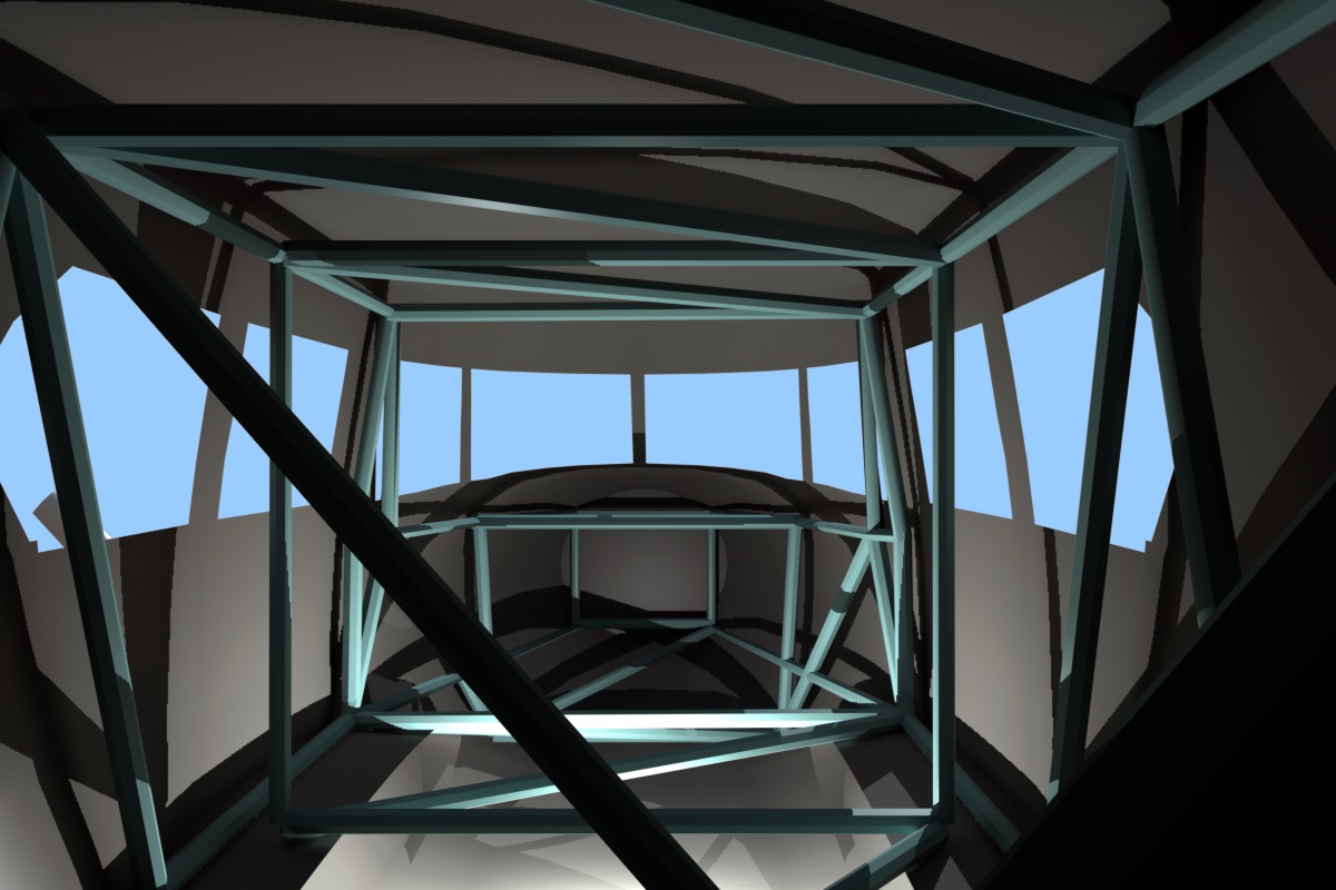
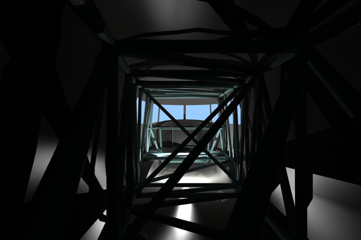
Some practice on the new internal structure:
I'll have some documentation soon, telling me things like the actual tubing diameters used in the aircraft's construction. In the meantime, I guessed it at 1 inch diameter, and did a run-through on how I'll make the internal tubing structure. The diameter looks a little large to me, but it's a convincing effect, and was a good practice for later... Lots of this kind of thing in the actual aircraft.
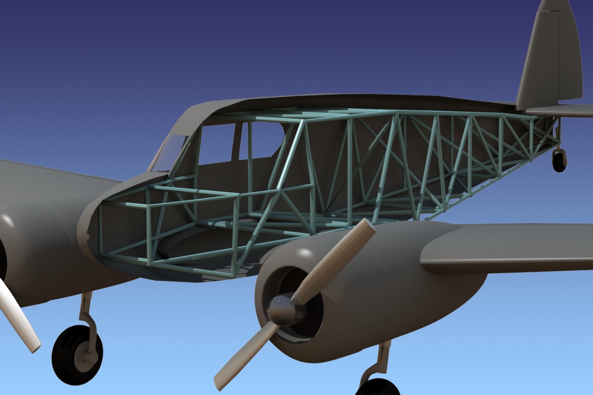
More accuracy on the internal tube structure
This time, I selected 3/4-inch diameter tubing for the main structure, and 1/2-inch diameter tubing for the smaller structures, like those around the top of the windscreen. Looks like the right size, and the position of all the parts shown is now accurate to the real aircraft. Next, I'll be adding the many wood frame parts and stringers that integrate with the tubing.
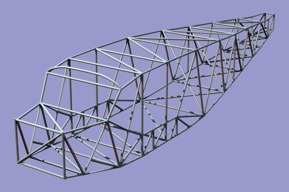
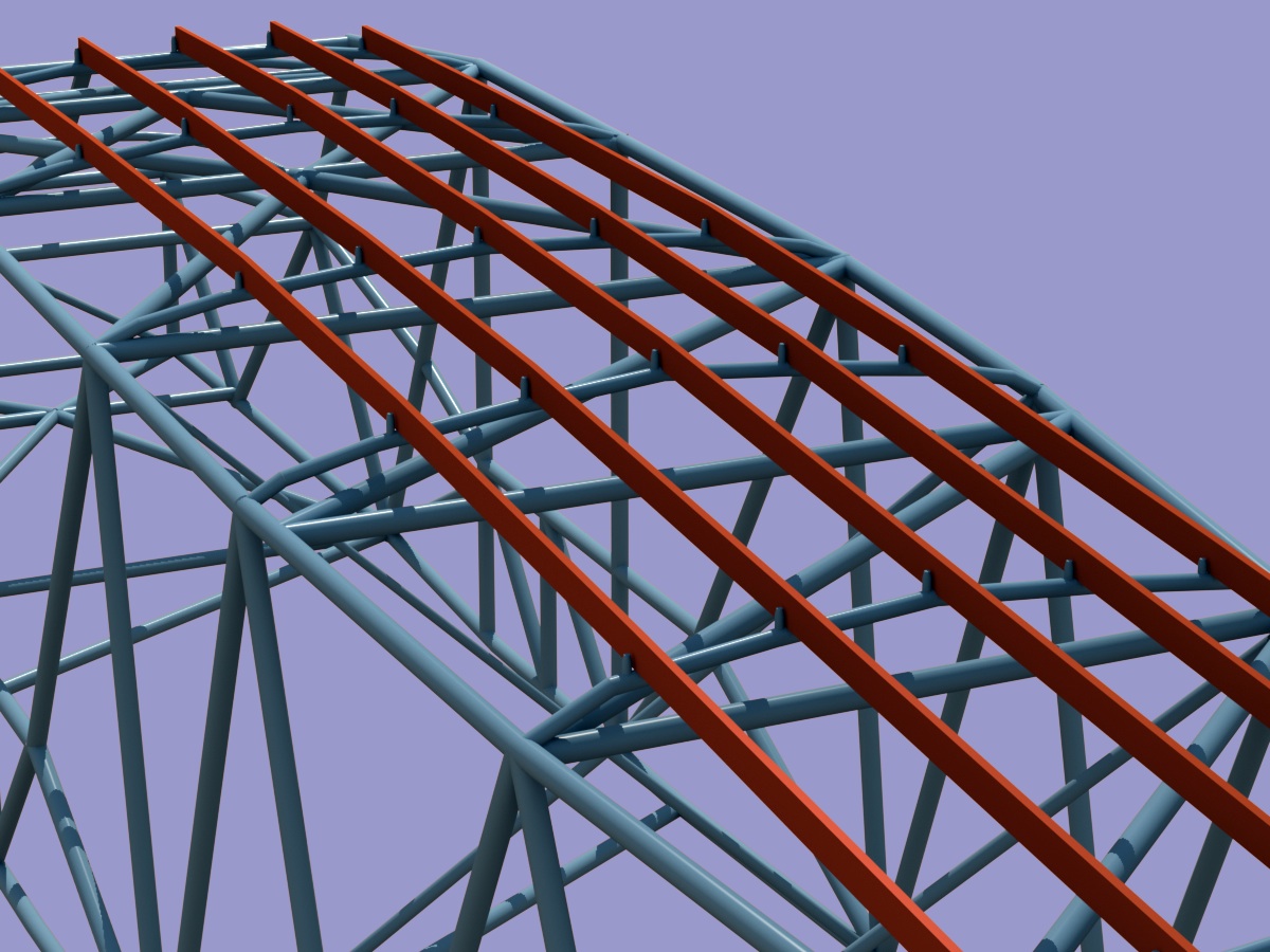
Finalized the tube structure, using factory specs.
Thanks to the help of Terry Sullivan, I was able to review some pages from the Cessna T-50 maintenance manual, and finalized the tube structure, according to the actual aircraft. Thank you, Terry! Part of that structure is the formers on top of the fuselage that help attach the wooden stringers that form the roof. There are a lot of wood supports too, but my goal was to do the metal parts first. The stringers were necessary, to help position everything else, and so they're accurate too.
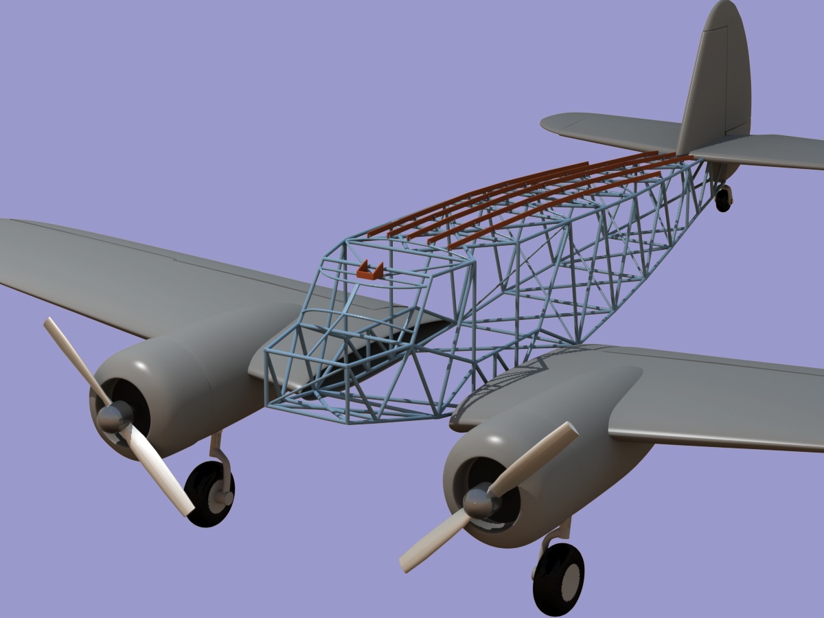
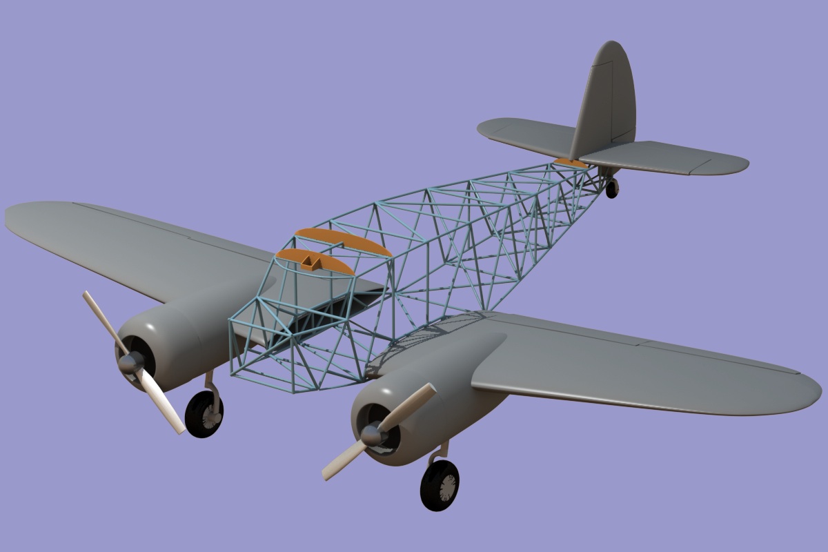
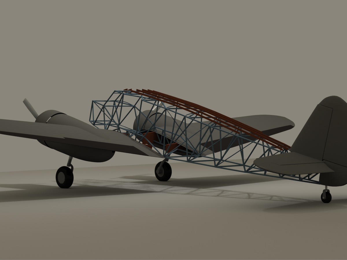
Did a little more tweaking of the tube structure, around the nose, and the fin/fuselage area, and I believe it's right now. I rebuilt the wing exterior, added the two main spars, and cut the flaps and ailerons free.
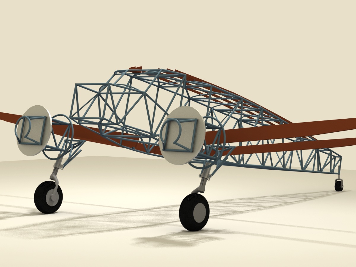
A start on the tubing structure for the landing gear and engine mounts.
Added windows and window frames
Better results on the truss...
The wing spars on this aircraft are one piece, and run the entire length of the wing. During this modeling phase, you'll see each wing looking as though it has separate spars, just because I sometimes model with symmetry on. (both wings at once) Later, I'll join the spars, to look like the original one-piece design.
As I get the documentation, I'll adjust various things that are already done. In the following images, for example, I've reduced the tubing diameter to scale, and have almost finished the tubing that makes up the landing gear/engine mount part of the truss.
Click the "Page 04" link below, to continue.
- Page 01
- Page 02
- Page 03
- Page 04
- Page 05
- Page 06
- Page 07
- Page 08
- Page 09
- Page 10
- Page 11
- Page 12
- Page 13
- Page 14
- Page 15