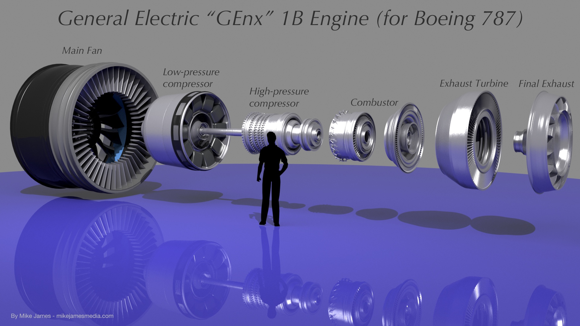
General Electric "GEnx" 1b Engine Rebuild/Up-Res:
Everything that follows here is related to the new (2013/2014) model.
NOTE: The images shown here are force-fit into the browser window, but the renders of this new version are actually much larger. (typically, 1920 X 1080) So, if you drag them to your desktop, you can see them in higher resolution.
Throughout this project, I've been extremely careful to model the engine in it's appropriate "modules", just as you might see them in real life, during maintenance. That's pleasing visually, but more importantly, it allows the model to be animated properly. For example, one of the unique features of the GEnx engine is that the main fan in front is attached directly to the exhaust turbine, and rotates clockwise, when viewed from the front. The other internal rotating parts (i.e., the compressor fans) rotate in the opposite direction. By building these modules separately, including the multi-part drive shaft, the engine can operate like the actual one does. I've even modeled the variable stators in the compressor, along with their linkages, so they can be animated too.
This is a "high-bypass turbofan". What that means is the main fan in front provides about 75 percent of the thrust, (pushing only clean, outside air) with only 25 percent being provided by the hot gas exiting from the exhaust turbine. The main fan is connected to the exhaust turbine, by a long shaft, and is a "free-wheeling" assembly. It's driven by hot exhaust gasses from the compressor and combustor. (not a "gearbox" of any kind)
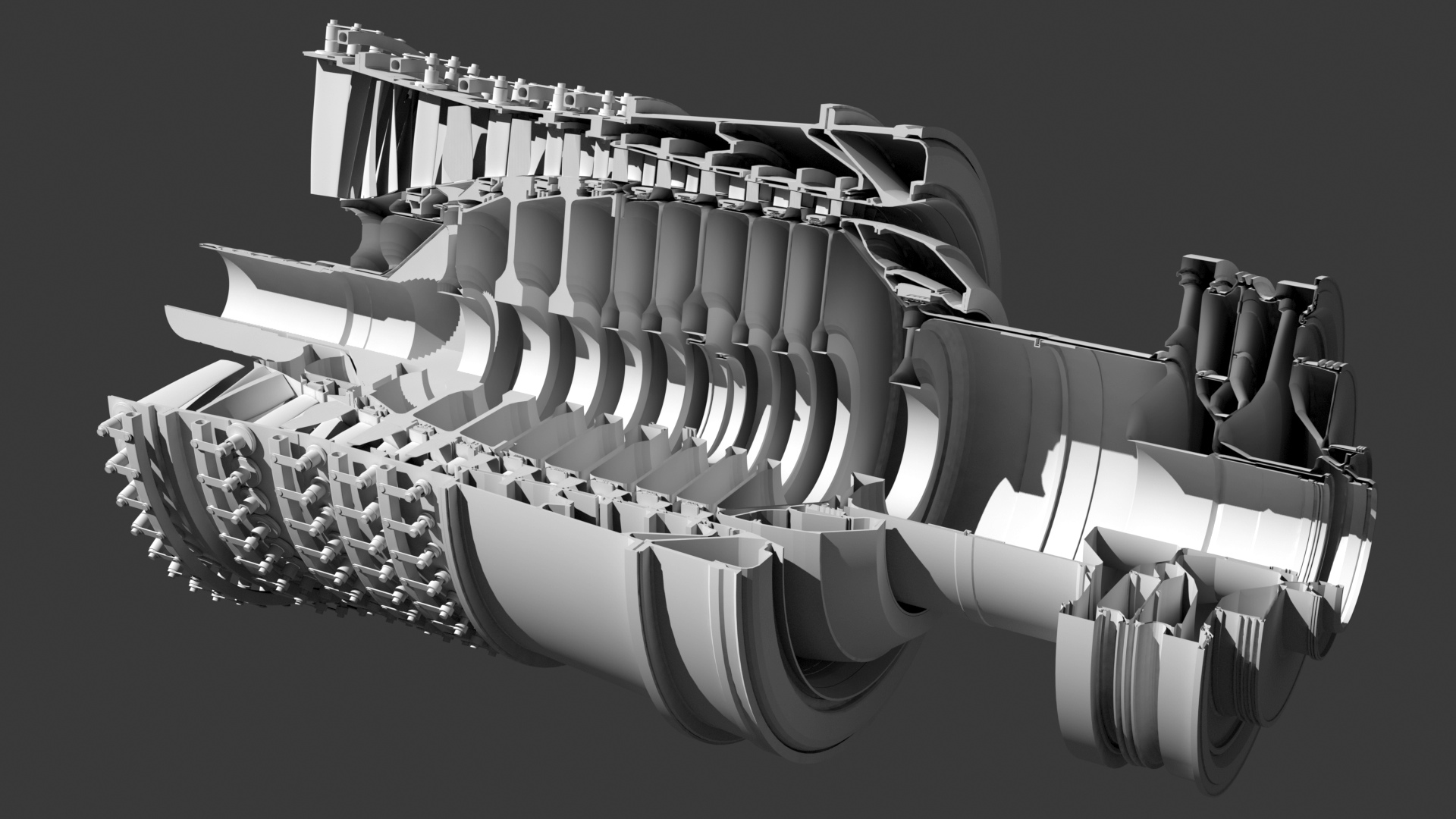
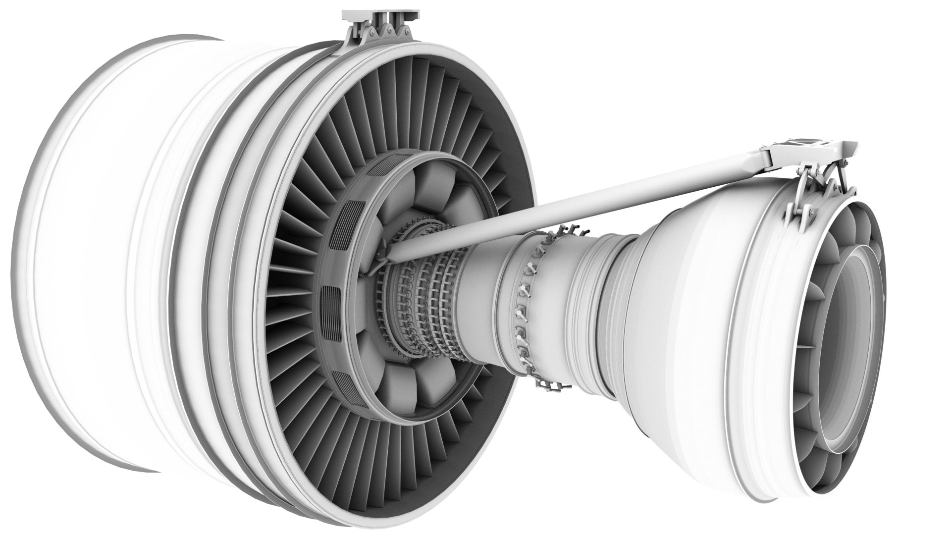
Above: Construction work on the high-pressure compressor
The second major improvement that you'll notice in the cutaway views is that now, all parts have real thickness, as they do in real life. (like the compressor image above) For most of the cutaway images, I'm using MODO's "render boolean" capability. Since these are polygonal models, and not true solids, the cutaway views allow you to see "between the layers" of the surfaces, but from an exterior (non-cutaway) point of view, they're solid.
Lots of geometry...
Although I could use MODO's "instancing" system to save geometry, I've chosen to use separate, actual geometry for every part, which enables me to export it in other formats, without having to convert it all. It does create a much larger file, but it's more cross-platform and "fool-proof".
Since this model was done three years after the first one, I've spent a lot more time on research, and understand the fundamental errors I made in the first engine. So, before even starting on the new version, I made sure I understood which parts rotate (and in what direction) and what each module actually does. I planned out the multi-part drive shaft first, followed by carefully correcting the shape of the main fan blades. This whole process is really quite fascinating, because in the general sense, turbine engines are "simple". But... There are a LOT of parts! By my count, (including the moving fan blades and both the variable and static stators, there are 2898 fan blades in this engine, plus a few exhaust vanes in the final section.
Details of the GEnx:
At this stage in the project, most of the major internal assemblies (drive shaft, fan disks and blades, etc.) are finished. What remains are a large number of items mounted to the exterior of the engine, (fuel lines, electronics and wiring, etc.) and as resources permit, a LOT of nuts and bolts. I've prioritized this project to show the most important structures first, and save the less-visible items for last. Often, the "simple" act of adding thousands of bolts and rivets can double the file size.
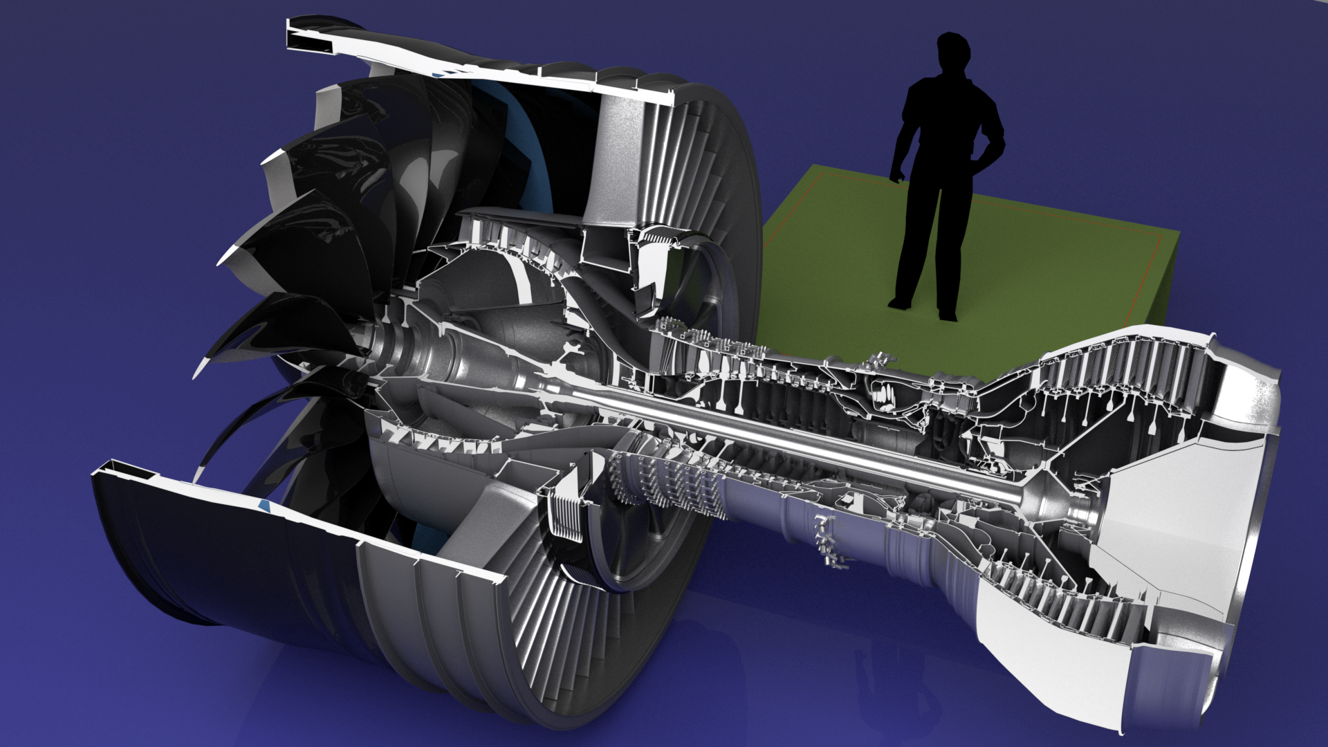
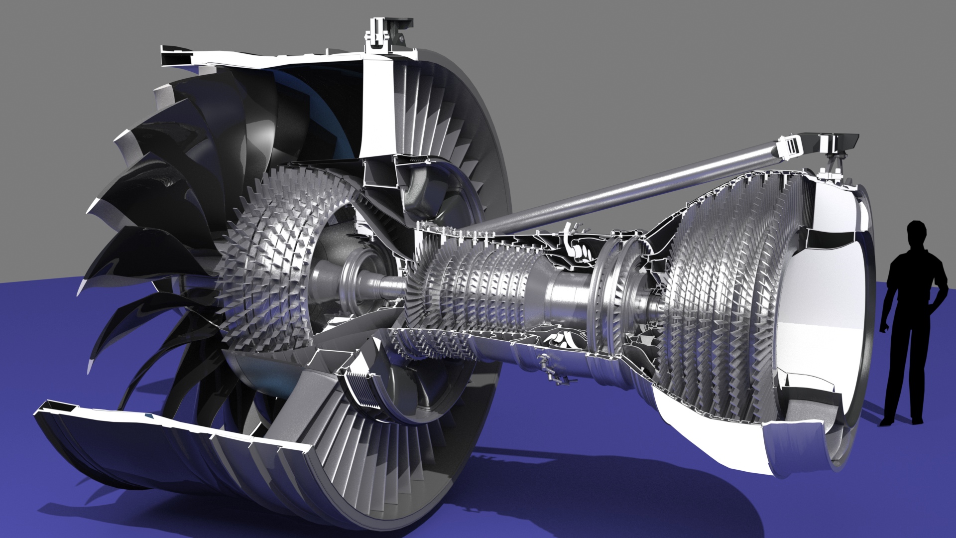
The difficulty in showing any detailed model is that you must get in close, to see the details. So, for example, when you do a cutaway-type render, it's important to consider which parts to cut away. Here are a couple of variations, one which shows the interior all the way down through the drive shaft, and one which lets you see all the fan and stator blades, along with some exterior parts, like the engine mounts. (Remember, you can drag these to your desktop to see them in much higher resolution.) I find myself doing a balancing act with the render times, too. Due to the sheer number of parts, and the fact that they contain a lot of metal materials means that renders like these can take several hours each. I'll need a much more powerful computer to do the animation this model was designed for.
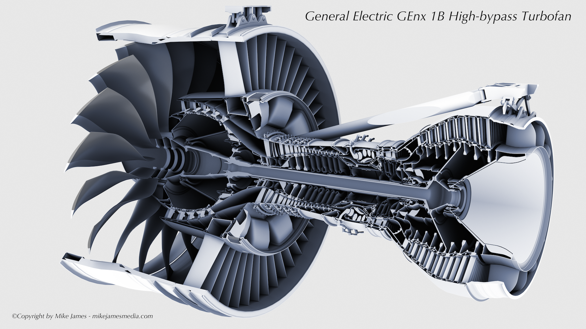
The whole engine

Below - The ambient occlusion output from modo (here with 512 occlusion rays) are really useful. They're sometimes quite interesting on their own, but can also be used effectively in Photoshop, to bring out various details in your images. I will often use an output like this on top of the other layers, in "Multiply" mode, set to about 10 percent opacity.
The video below is simply a slideshow of renders made during the high-res model's building, to give you a feel for the structures.
This movie may take a few moments to load.